5 Electrical Connection User Manual
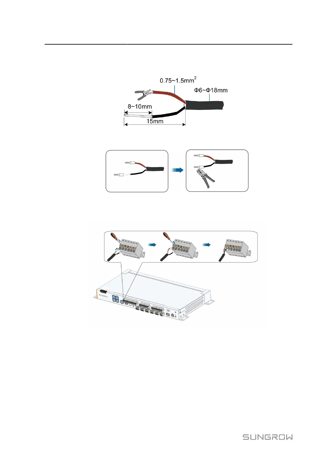
step 1 Strip the protection layer and insulation layer of the dry contact input signal cable with a wire
striper, as shown in the figure below.
step 2
Install cord-end terminals and crimp them with crimping pliers.
step 3
Connect the cord end terminals to the plug "DI" outside the Data Logger, as shown below. Port
"OV" and Port "1" are taken as an example.
- - End
5.8 Wiring of DO Signal
Port 1 corresponds to NO, port 2 to NC, and port 3 to COM. NO/COM is the normally open
contact, and NC/COM is the normally closed contact. It is recommended that the signal
transmission distance not exceed 10m.
32
 Loading...

