5 Electrical Connection User Manual
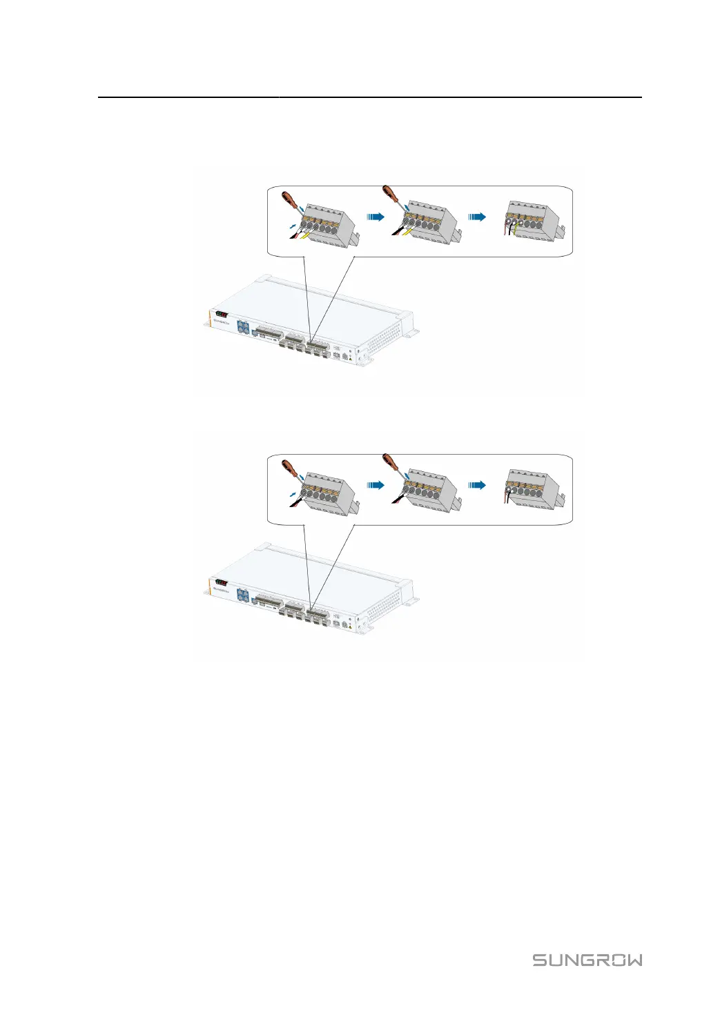
step 3 Connect the cord end terminals to plugs “PT1”~”PT4" outside the Data Logger, as shown below.
Port “PT1" is taken as an example.
figure 5-1 3–wire PT100/PT1000 connection
figure 5-2 2–wire PT100/PT1000 connection
- - End
5.11 Connecting to the Remote Monitoring Device
The Data Logger can be connected to the background with an Ethernet switch or a router.
The Data Logger is equipped with three Ethernet ports: ETH1, ETH2 and ETH5. Access
the Ethernet switch and the router through either port. This section takes connecting to an
Ethernet switch as an example to illustrate the wiring steps.
36
 Loading...

