Home
Tektronix
Test Equipment
DPO77002SX
Tektronix DPO77002SX User Manual
5
of 1
of 1 rating
230 pages
Give review
Manual
Specs
To Next Page
To Next Page
To Previous Page
To Previous Page
Loading...
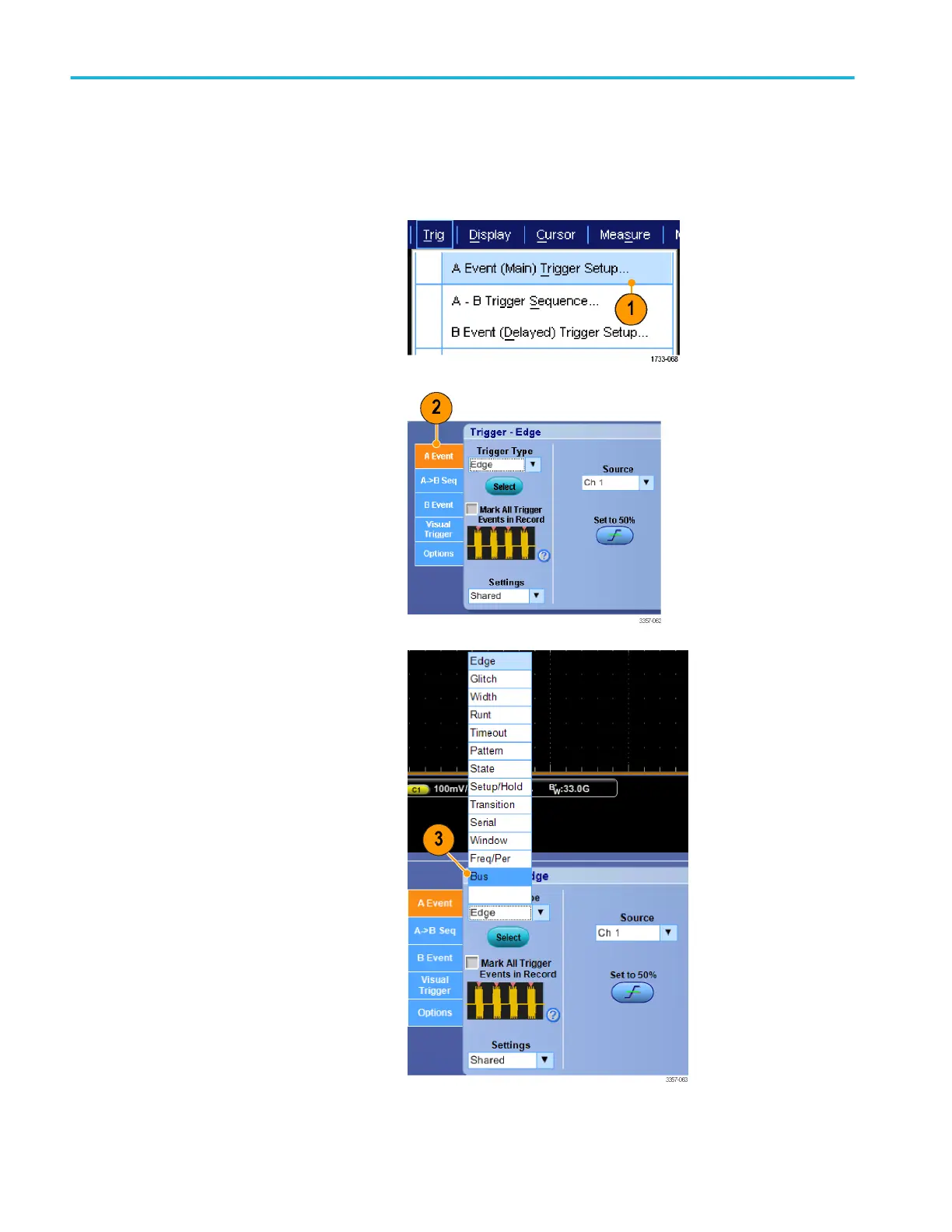
Triggering on a parallel bus
Locate problems by triggering on a parallel bus.
1.
Set up a parallel bus. See
Setting up a
bus
on page 68. Select
Trig > A Event
(Main) Trigger Setup...
.
2.
Select the A Event tab.
3.
Select the
Bus
Trigger Type.
Pinpoint triggers
94
DPO70000SX Series User
113
115
Table of Contents
Default Chapter
5
Table of Contents
5
Important Safety Information
11
General Safety Summary
11
Service Safety Summary
13
Terms in the Manual
13
Terms on the Product
13
Symbols on the Product
13
Compliance Information
15
EMC Compliance
15
Safety Compliance
16
Environmental Compliance
17
Preface
19
Install Your Instrument
21
Standard Accessories
21
Operating Requirements
22
Power Supply Requirements
23
Preventing Instrument Damage
23
Preventing ESD
23
Observe Maximum Input Voltage
25
Selecting the Proper Attenuator
25
Connector Cleaning
25
Proper Connection Technique
26
Power on the Instrument
29
Power off the Instrument
30
Multi-Instrument Configuration
30
Instrument Stacking
30
Before Startup
33
Ultrasync ™ Bus Cable
33
Ultrasync ™ Bus Cable Connection Order
33
Master and Extension Connection Order
35
Multi-Instrument Power on
36
Switching between Multi-Instrument Modes
40
ATI Versus Tekconnect Channels
41
Multi-Instrument Status Displays
42
Available Features
42
DPO7AFP Auxiliary Front Panel (Optional)
43
Inspect the Instrument
43
Verify Internal Diagnostics Pass
43
Activating Windows 10
44
Windows Interface Guidelines
45
Signal Path Compensation
46
Connecting to a Network
49
Adding a Second Monitor
50
Activating Windows 10
50
Restoring Instrument Operating System and Product Software
51
Operating System Restore
51
Internal Recovery Utility
51
Product Software Installation
52
Getting Acquainted with Your Instrument
53
Front-Panel Connectors
53
Rear-Panel Connectors
55
Interface and Display
56
Control Panel
58
Accessing Online Help
59
Accessing Menus and Control Windows
60
Inspect Your Instrument
61
Verify Internal Diagnostics Pass
61
Acquisition
63
Signal Path Compensation
63
Setting up Analog Signal Input
66
Using Default Setup
68
Using Autoset
69
Probe Compensation and Deskew
70
Deskew Tool
70
Acquisition Concepts
75
Acquisition Hardware
75
Sampling Process
76
Real-Time Sampling
76
Interpolated Real-Time Sampling
76
Equivalent-Time Sampling
76
Waveform Record
77
Interpolation
77
How the Acquisition Modes Work
77
Enable Enhanced Effective Number of Bits
78
Changing the Acquisition Mode
79
Starting and Stopping an Acquisition
80
Selecting the Horizontal Mode
81
Using Fastacq
83
Using DSP Enhanced Bandwidth
84
Setting the Termination Voltage
86
Using Roll Mode
87
Setting up a Bus
88
Set up a Serial Bus
90
Set up a Parallel Bus
91
Set up Bus Display
93
Using Fastframe Mode
94
Using Fastframe Frame Finder
96
Pinpoint Triggers
99
Triggering Concepts
99
Trigger Event
99
Trigger Modes
99
Trigger Holdoff
99
Trigger Coupling
100
Horizontal Position
100
Slope and Level
100
Delayed Trigger System
100
Choosing a Trigger Type
101
Trigger Selections
103
Checking Trigger Status
104
Using a (Main) and B (Delayed) Triggers
105
Trigger on B Event
106
B Trigger after Delay Time
106
B Triggers after Arm on a
106
Arm-On-A then Trigger-On-B (Horizontal Delay On)
107
Vertical Setup Control Window (M Chx Tab)
108
Triggering with Reset
109
Correcting Trigger Position
110
Triggering with B-Event Scan
111
Triggering on a Parallel Bus
114
Triggering on a Serial Bus
116
Triggering Using Visual Triggers (Visual Triggering)
118
Setting up Action on Event
120
Sending E-Mail on Trigger
121
Setting up E-Mail on Event
122
Using Horizontal Delay
124
Display a Waveform
125
Setting the Display Style
125
Setting the Display Persistence
126
Setting the Display Format
127
Selecting the Waveform Interpolation
128
Adding Screen Text
129
Setting the Graticule Style
130
Setting the Trigger Level Marker
131
Displaying the Date and Time
131
Using the Color Palettes
132
Setting Reference Waveform Colors
133
Setting Math Waveform Colors
134
Using Multiview Zoom
135
Zooming in Multiple Areas
136
Lock and Scroll Zoomed Waveforms
138
Hide Waveforms in the Zoomed Window
139
Searching and Marking Waveforms
139
To Manually Set and Clear (Delete) Marks
140
To Automatically Set and Clear (Delete) Search Marks
142
Using a Visual Search
147
Analyzing Waveforms
149
Taking Automatic Measurements
149
Automated Measurement Selections
150
Customizing an Automatic Measurement
153
Gating
154
Statistics
154
Snapshot
155
Annotate Measurements
155
Reference Levels
156
Taking Cursor Measurements
158
Setting up a Histogram
160
Using Math Waveforms
162
Using Spectral Analysis
165
Using the Error Detector
168
Using Mask Testing
172
Using Limit Testing
175
Myscope
177
Creating a New Myscope Control Window
177
Using Myscope Control Windows
181
Saving and Recalling Information
183
Saving Screen Captures
183
Saving Waveforms
185
Recalling Waveforms
187
Saving Instrument Setups
188
Recalling Instrument Setups
189
Saving Measurements
190
Saving User Masks
191
Saving Histogram Data
192
Saving Timestamps
193
Copying Your Results to the Clipboard
194
Printing a Hard Copy
196
Run Application Software
197
Application Examples
199
Capturing Intermittent Anomalies
199
Using the Extended Desktop and Openchoice Architecture for Efficient Documentation
202
Triggering on Buses
204
Specifications
207
Vertical System Analog Channels
207
Horizontal and Acquisition System
211
Trigger Specifications
212
Input-Output Port Specifications
214
Power Source Specification
214
Mechanical Specifications
215
Environmental Specifications
215
Appendix A, Maintenance
217
Maintenance
217
Cleaning
217
Exterior Cleaning
217
Adjustment Interval
218
Adjustment
218
Flat Panel Display Cleaning
218
Returning the Instrument for Service
219
Tekscope Recovery Report Utility
219
Replaceable Parts
221
Parts Ordering Information
222
Appendix B, Version Releases
223
Obtaining the Latest Advanced Analysis Application and Version Releases
223
Other manuals for Tektronix DPO77002SX
Printable Help
920 pages
Installation And Safety Manual
90 pages
5
Based on 1 rating
Ask a question
Give review
Questions and Answers:
Need help?
Do you have a question about the Tektronix DPO77002SX and is the answer not in the manual?
Ask a question
Tektronix DPO77002SX Specifications
General
Brand
Tektronix
Model
DPO77002SX
Category
Test Equipment
Language
English
Related product manuals
Tektronix DPO7354
213 pages
Tektronix DPO7104C
222 pages
Tektronix DPO7354C
222 pages
Tektronix DPO7054C
222 pages
Tektronix DPO7254C
222 pages
Tektronix DPO70804C
222 pages
Tektronix DPO71604C
222 pages
Tektronix DPO73304DX
222 pages
Tektronix DPO7000 Series
213 pages
Tektronix DPO70000 Series
213 pages
Tektronix DPO70000C Series
222 pages
Tektronix DPO70000C/DX Series
1002 pages