REMARKS
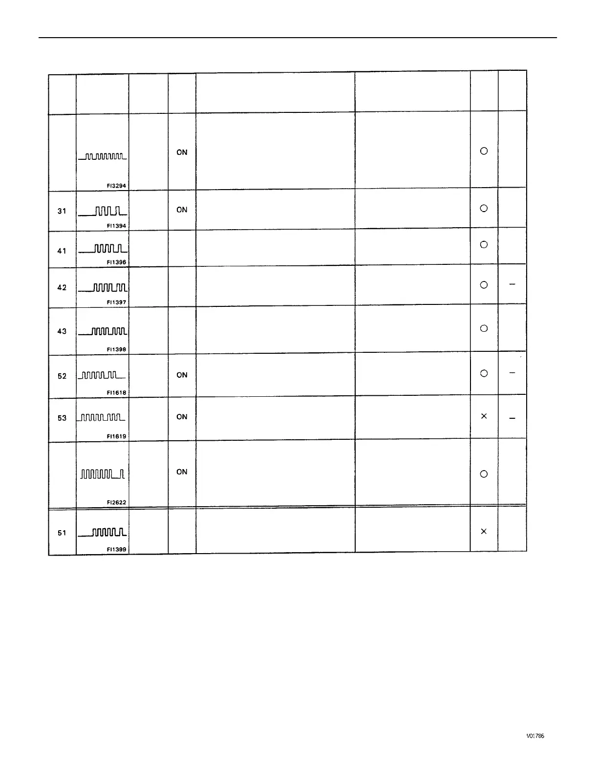
*1: ”ON” displayed in the diagnosis mode column indicates that the Malfunction Indicator Lamp is
lighted up when a malfunction is detected.
”OFF” indicates that the MIL does not light up during malfunction diagnosis, even if a malfunction is
detected.
*2: ”0” in the memory column indicates that a diagnostic code is recorded in the ECM memory when a
malfunction occurs. ” x ” indicates that a diagnostic code is not recorded in the ECM memory even if
a malfunction occurs. Accordingly, output of diagnostics results is performed with the IG SW ON.
*3: The ”Malfunction Indicator Lamp comes on if malfunction occurs only for California specifications.
*4: No. (2) in the diagnostic contents of codes No.25 and 26 apply to California specification vehicles
only. While
(1) applies to all models.
*5: Codes 27 and 71 are used only for California specifications.
*6: ”2 trip detection logic” (See page EG1–112)
(1) When sub–oxygen sensor is warmed up
and full acceleration continued for 2 seconds,
output of main oxygen sensor is 0.45 V or
more (rich) and output of sub–oxygen sen–
sor is 0.45 V or less (lean). (OX2)
(2) Open or short detected continuously for
500 msec. or more in sub–oxygen sensor
heater circuit
*6 (2 trip detection logic) (1) and (2)
With the coolant temp. at 65C (149F) or
more, 50 seconds from start of EGR opera–
tion. The EGR gas temp. is less than 70C
(158F) and the EGR gas temp. has risen
less than 3C during the 50 seconds.
*6 (2 trip detection logic)
Open or short detected continuously for
500 msec. or more in volume air flow meter
circuit
• Open – VC or E2
• Short – VC–E2 or VS–VC
Displayed when IDL contact OFF or shift
position in ”R”, ”D”, ”2”, or ”’I” ranges
with the check terminals E1 and TE1 con–
nected.
SPD signal is not input to the ECM for at
least 8 seconds during high load driving
with engine speed between 2,200 rpm
and 5,000 rpm.
• Short or open in sub–oxygen
sensor circuit
• Sub–oxygen sensor
• Open or short in sub–oxygen
sensor heater
• ECM
• Open or short in starter signal
circuit
• Open or short in IG SW or
main relay circuit
• ECM
Starter signal (STA) is not input to ECM
even once until engine reaches 800 rpm or
more when cranking.
DIAGNOSTIC TROUBLE CODES (Cont’d)
With engine speed 2,000 rpm or more
signal from knock sensor is not input to
ECM for 25 revolution. (KNK)
• Open or short in volume air
flow meter circuit
• Volume air flow meter
• ECM
Open or short detected in throttle position
sensor signal (VTA) for 500 msec. or more.
• Open or short in throttle
position sensor circuit
• Throttle position sensor
• ECM
• Open or short in vehicle
speed sensor circuit
• Vehicle speed sensor
• ECM
The engine control computer (for knock
control) malfunction is detected.
Number of
blinks
Malfunction
Indicator
Lamp
Volume
Air
Flow
Meter
Signal
Throttle
Position
Sensor
Signal
EGR
System
Mal–
function
Sub–
Oxygen
Sensor
Signal
Vehicle
Speed
Sensor
Signal
Switch
Condition
Signal
EG1–138
EG1–156
EG1–174
EG1–128
EG1–146
EG1–164.
EG1–140
EG1–158
EG1–176
EG1–127
EG1–145
EG1–163
EG1–132
EG1–150
EG1–168
Knock
Control
Signal
EG1–129
EG1–147
EG1–165
Knock
Sensor
Signal
Trouble Area
Starter
Signal
*2
Memory
Diagnosis
Code
No.
See
Page
System
–3
ON
*5
71
*5
27
• ECM
OFF
OFF
OFF
MIL
• Open or short in knock signal
circuit
• Knock sensor (looseness,
ect.)
• ECM
• Open in EGR gas temp.
sensor circuit
• Open in VSV circuit for EGR
• EGR vacuum hose discon–
nected, valve stuck
• Clogged in EGR gas pas-
sage
• ECM
• Throttle position sensor IDL
circuit
• PNP switch circuit
• Accelerator pedal, cable
• ECM
–ENGINE MFI SYSTEM
EG1–115

 Loading...