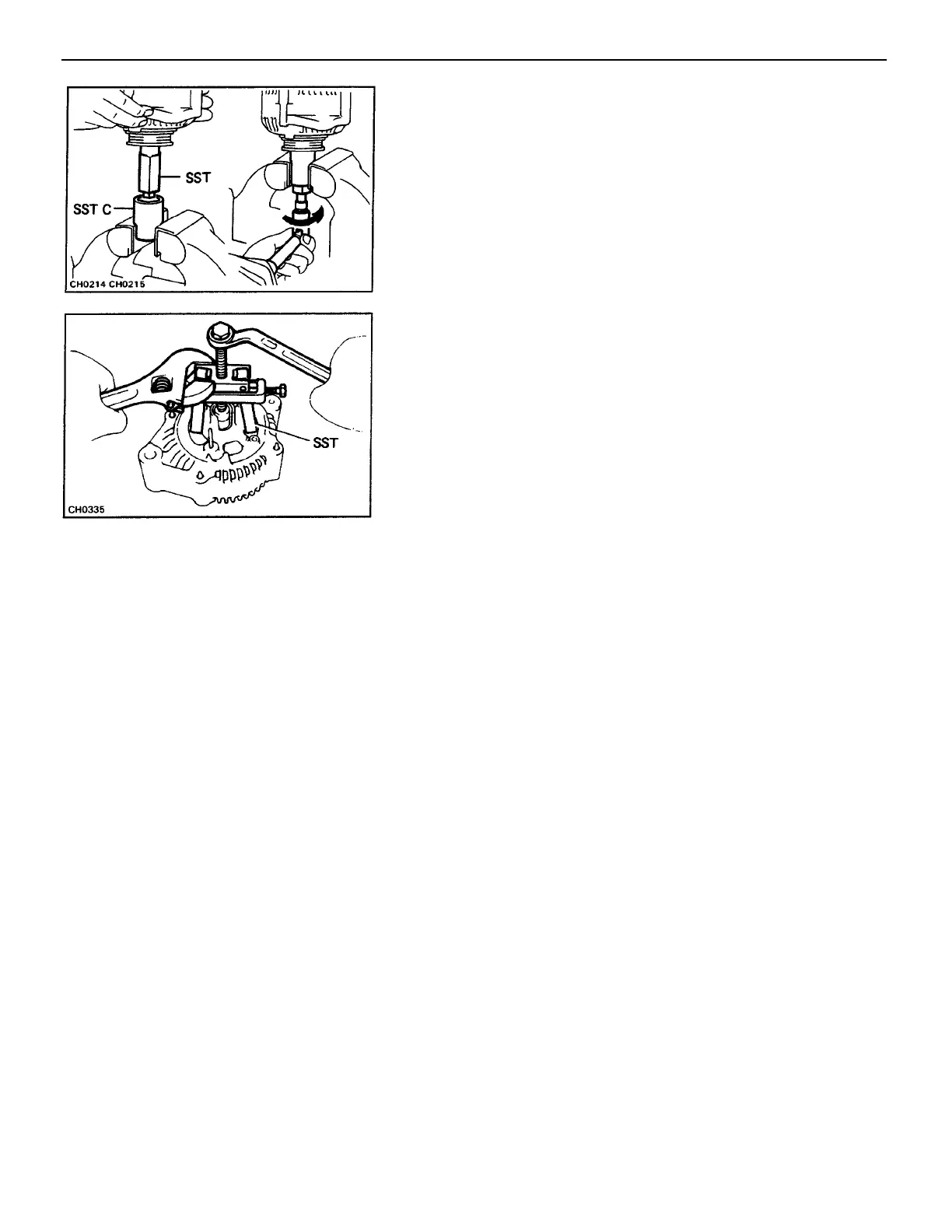
(c) As shown in the illustration, mount SST C in a vise,
and install the generator with SST (A and B) to SST C.
(d) To loosen the pulley nut, turn SST A in the direction
shown in the illustration.
NOTICE: To prevent damage to the rotor shaft, do not
loosen the pulley nut more than one–half of a turn.
(e) Remove the generator with SST (A and B) from SST C.
(f) Turn SST B and remove SSTs A and B.
(g) Remove the pulley nut and pulley.
6. REMOVE REAR END FRAME
(a) Remove the four nuts.
(b) Using SST, remove the¿ rear end frame.
SST 09286–46011
7. REMOVE ROTOR FROM DRIVE END FRAME
–CHARGING SYSTEM Generator
CH–9
 Loading...