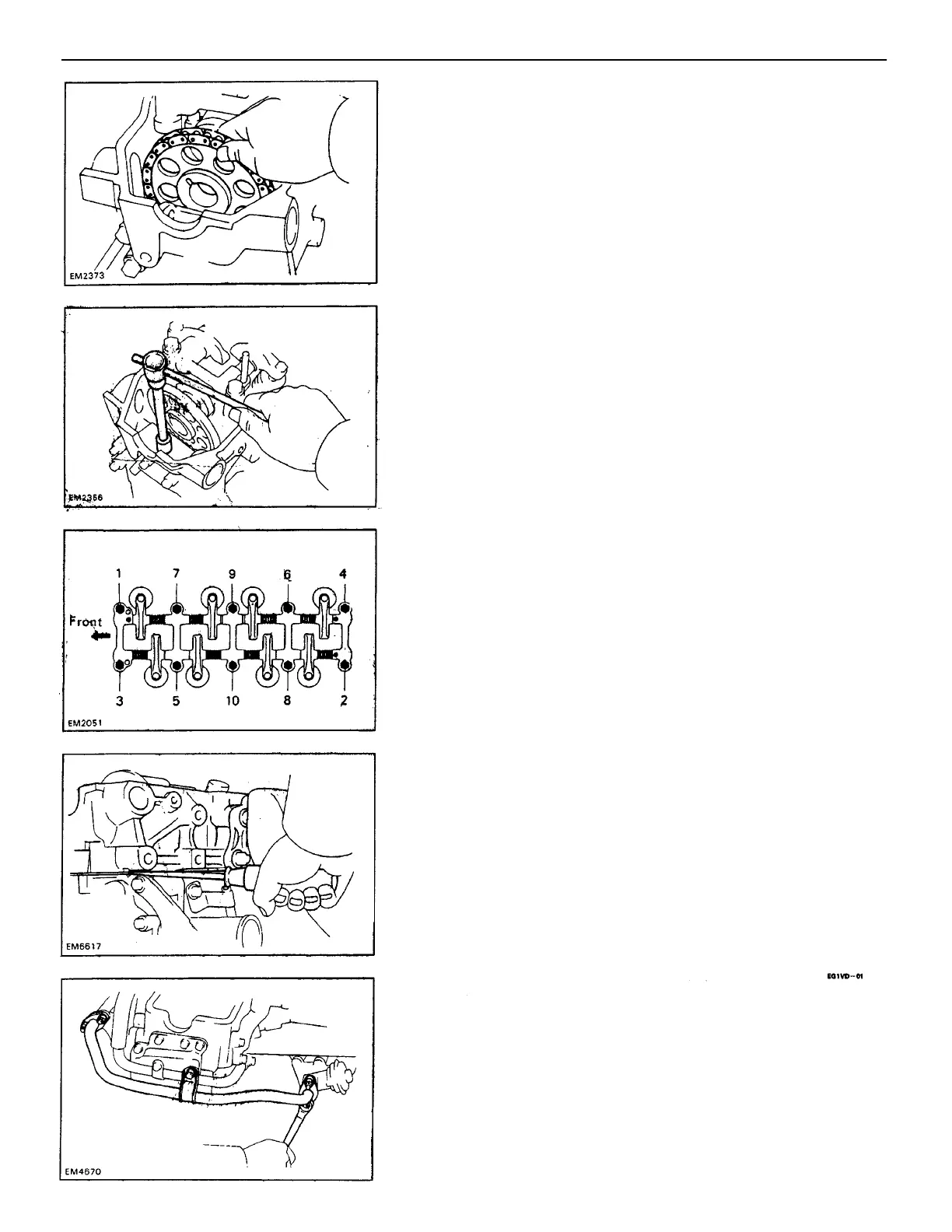
6. REMOVE CYLINDER HEAD BOLTS
Remove the head bolts gradually in two or three
passes and in the numerical order shown.
NOTICE: Head warpage or cracking could result from
removing bolts incorrect order.
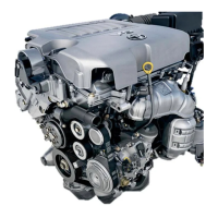
7. REMOVE ROCKER ARM ASSEMBLY
If may be necessary to use a pry bar on the front and
rear of the rocker arm assembly to separate it from
the head.
8. REMOVE CYLINDER HEAD
Lift the cylinder head from the dowels on the cylinder
block and place the head on wooden blocks on a
bench.
HINT: If the cylinder head is difficult to lift off, pry
with a screwdriver between the head and block sa–
liences.
NOTICE: Be careful not to damage the cylinder head and
block surfaces of the cylinder head gasket.
CYLINDER HEAD DISASSEMBLY
(See page EG1–15)
1. REMOVE NO. 1 SECONDARY AIR INJECTION
MANIFOLD
Remove the bolt, four nuts, No. 1 secondary air in–
jection manifold and two gaskets.
5. REMOVE CHARY COVER BOLT
Remove the bolt in.–front of the head before the other
head bolts are removed.
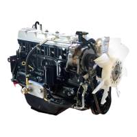
4. REMOVE CAM SPROCKET
Remove the cam sprocket and chain from the cam–
shaft and leave on the vibration damper.
–ENGINE ENGINE MECHANICAL
EG1–19
 Loading...