Lubrication
Removal
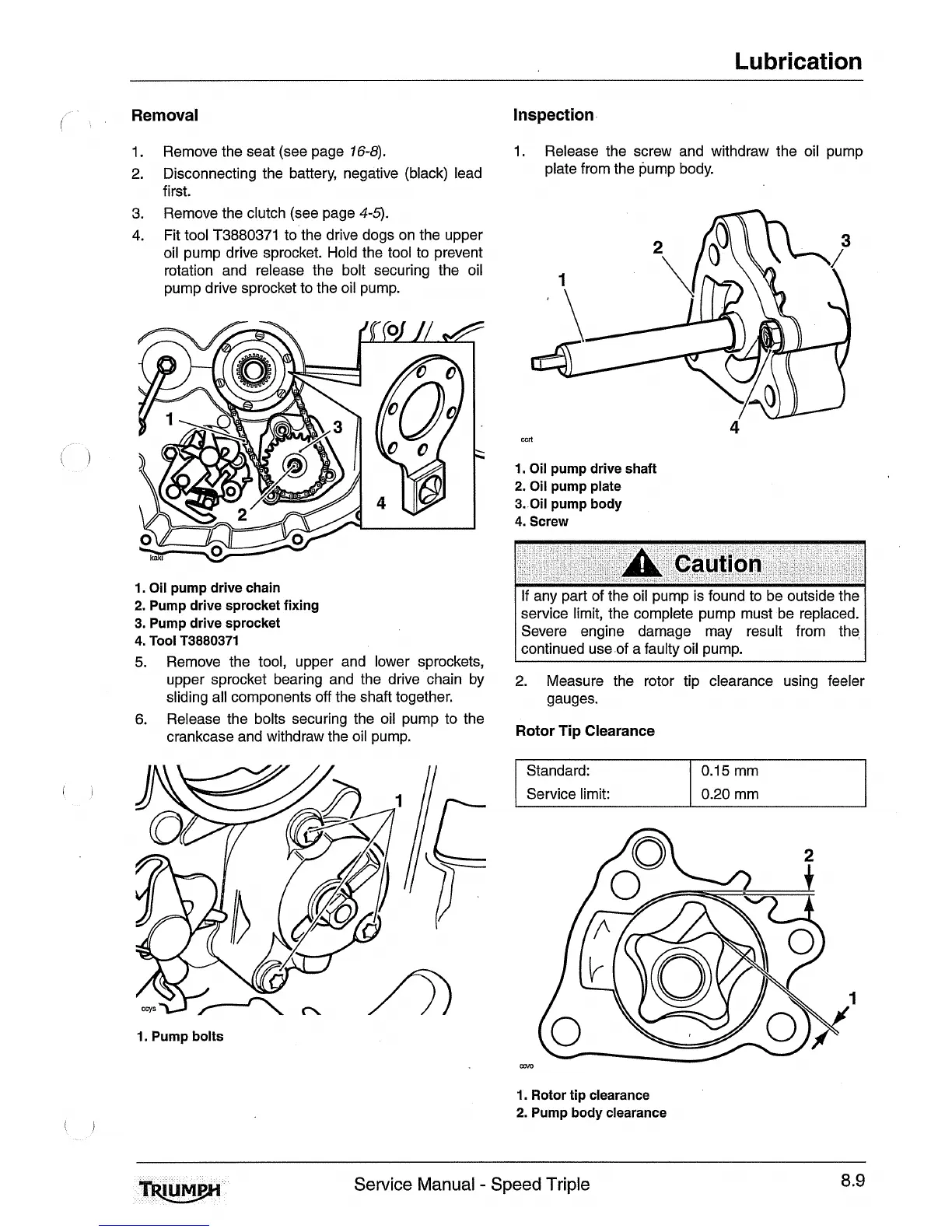
Inspection
1.
Remove the seat (see page
16-8).
2.
Disconnecting the battery, negative (black) lead
first.
3.
Remove the clutch (see page
4-5).
4.
Fit tool T3880371 to the drive dogs on the upper
oil pump drive sprocket. Hold the tool to prevent
rotation and release the bolt securing the oil
pump drive sprocket to the oil pump.
1. Oil pump drive chain
2.
Pump drive sprocket fixing
3. Pump drive sprocket
4.
Tool T3880371
5.
Remove the tool, upper and lower sprockets,
upper sprocket bearing and the drive chain by
sliding all components off the shaft together.
6.
Release the bolts securing the oil pump to the
crankcase and withdraw the oil pump.
1. Pump bolts
1. Release the screw and withdraw the oil pump
plate from the pump body.
1. Oil pump drive shaft
2.
Oil pump plate
3. Oil pump body
4.
Screw
A
Caution
I
If any part of the oil pump is found to be outside the
I
service limit, the complete pump must be replaced.
Severe engine damage may result from the
continued use of a faulty oil pump.
2. Measure the rotor tip clearance using feeler
gauges.
Rotor
Tip
Clearance
I
Standard:
1
0.15 mm
I
I
Service limit:
1
0.20 mm
1. Rotor tip clearance
2.
Pump body clearance
Service Manual
-
Speed Triple
8.9

 Loading...