G 25 Schematics, Machines with Basler Controller
wc_tx003547gb_FM10.fm
201
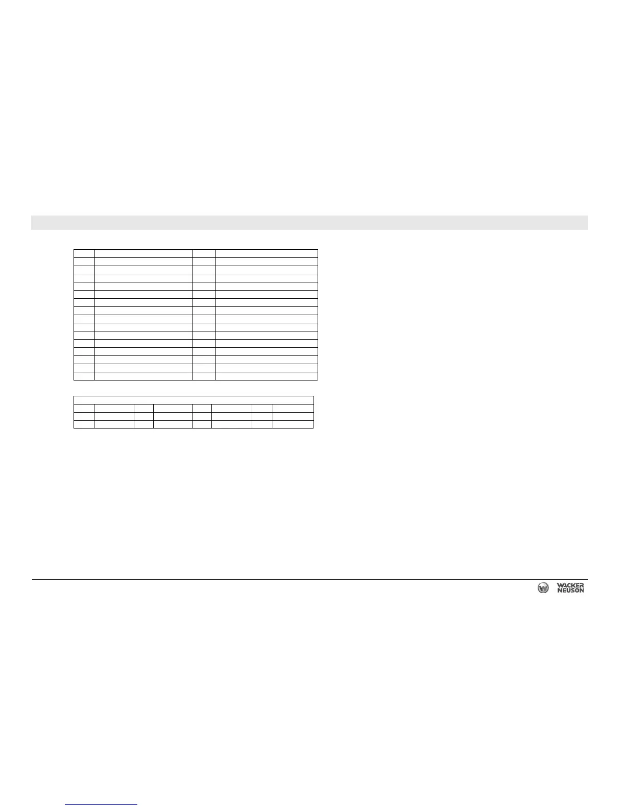
24.2 AC Schematic Components:
Ref. Description Ref. Description
1 Lug safety limit switch 16 Generator
2 Mechanical lugs 17 Voltage regulator with 4A fuse
3 Plug 3 - current transformer inputs 18 Voltage adjustment rheostat
4 Plug 4 - line voltage inputs 19 Terminal block
5 Shunt 20 Exciter rotor windings
6 120V GFI receptacle 21 Exciter stator winding
7 120V 20A breaker 22 Rotor
8 240V 50A breaker 23 Rectifier (diodes)
8a 240V 20A breaker (optional) — —
10 240V 50A receptacle 24 Main rotor winding
10a 240V 20A receptacle (optional) — —
12 Engine control module 25 Main stator windings
13 Main breaker 26 Auxiliary stator winding
14 Bus bar 27 Stator
15 Voltage selector switch 28 Exciter
Wire Colors
BLK Black RED Red WHT White ORG Orange
GRN Green TAN Tan YEL Yellow — —
BLU Blue VIO Violet GRY Gray — —

 Loading...