G 25 Schematics, Machines with Basler Controller
wc_tx003547gb_FM10.fm
205
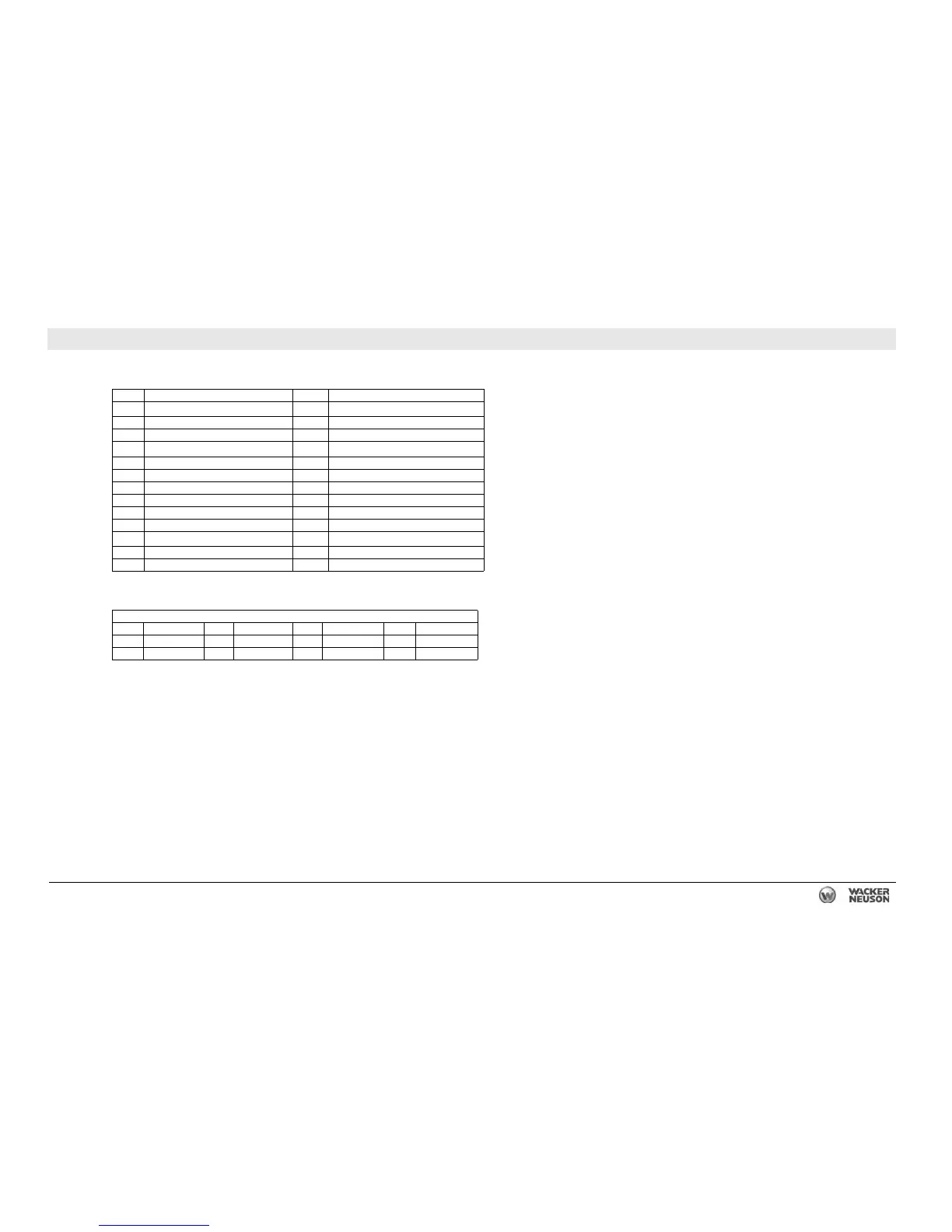
24.6 DC Schematic Components: G 25, T4f Isuzu, Basler
Ref. Description Ref. Description
1
Plug 1 - power and engine sender inputs
14
Idle switch
2 Plug 2 - contact inputs 15 Battery disconnect (optional)
3 Electronic control unit (genset controller) 16 Shunt trip relay
4
Plug 4 - E-stop & contact outputs
17
Bond bar
5 Water temperature sender 18 Emergency stop switch
6 Remote start / Off / Start/Run switch 19 Remote start terminals
7 Relay - engine outputs 20 Battery
8 Hour meter 21 Starter motor
9 1A fuse 22 Engine connector
10 10A fuse 23 Mechanical lugs
11
Lug door interlock switch
24
Main circuit breaker
12 Terminal strip 25 Fuel level sender
13 7.5A fuse — —
Wire Colors
BLK Black RED Red WHT White ORG Orange
GRN Green TAN Tan YEL Yellow — —
BLU Blue VIO Violet GRY Gray — —

 Loading...