G 25 Schematics, Machines with Deep Sea Controller
wc_tx003700gb_FM10.fm
211
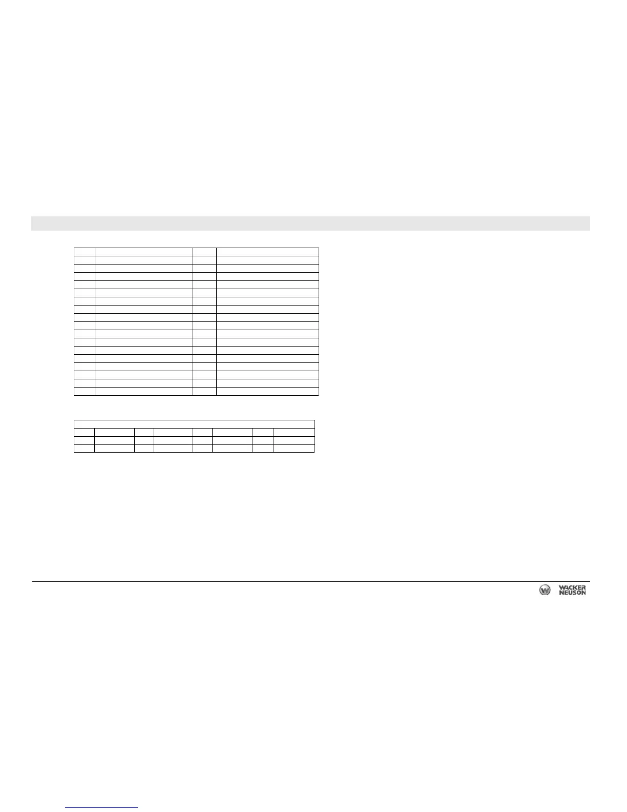
25.4 DC Schematic Components: G 25, T4i Isuzu, Deep Sea
Ref. Description Ref. Description
1 Plug 1 - power and engine sender inputs 18 Emergency stop switch
2 Plug 2 - contact inputs 19 Remote start terminals
3 Electronic control unit (genset controller) 20 Battery
4 Oil pressure sender 21 Starter motor
5 Water temperature sender 22 Alternator
6 ON/OFF toggle switch 23 Mechanical lugs
7 Relay - engine outputs 24 Main circuit breaker
8 Hour meter 25 Fuel level sender
9 Fuel pump 26 Lug door interlock switch
10 10A fuse 27 Bond bar
11 — 28 Shunt trip relay
12 Magnetic pickup 29 Battery disconnect (optional)
13 7.5A fuse 30 —
14 Glow plugs 31 Actuator
15 Glow plug relay 32 Electronic governor module
16 Fuel relay 33 Terminal strip
17 Starter relay 34 Shunt
Wire Colors
BLK Black RED Red WHT White ORG Orange
GRN Green TAN Tan YEL Yellow — —
BLU Blue VIO Violet GRY Gray — —

 Loading...