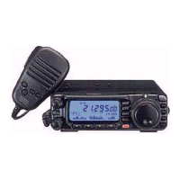
Installation
ANTENNA CONSIDERATIONS
The antenna systems connected to your FT-I 00 transceiver are,
of
course, critically impor-
tant
in
ensuring successful communications. The FT-IOO
is
designed for use with any an-
tenna system providing a
son
resistive impedance at the desired operating frequency.
While minor excursions from the
son
specification are
of
no
consequence, the power
amplifier's protection circuitry will begin to reduce the power output
of
there
is
more than
a
50% divergence from the specified impedance (less than
33n
or greater than
75n,
corre-
sponding to a Standing Wave Ratio (SWR)
of
1.5:
1).
Two antenna connector "pigtails" are provided on the rear panel
of
the FT -100. The "AN-
TENNA
1"
connection
is
used for HF and 50 MHz, while the "ANTENNA
2"
connector
is
used for 144 MHz and 430 MHz.
Guidelines for successful base and mobile station installations are shown below.
Mobile Antenna Installations
Mobile antennas for the HF bands, with the possible exception
of
those designed for 28
MHz, display very high
"Q" due to the fact that they must be physically shortened, then
resonated using a loading coil. Additional system bandwidth may be realized using the
Yaesu
FC-20
Automatic Antenna Tuner, which will present a
son
impedance to your
transceiver on the
1.8
~
50 MHz bands so long as the SWR on the coaxial line connected
to the
FC-20
is
below 3:
1.
On the VHF and UHF bands, coaxial line losses increase so rapidly in the presence
of
SWR that
we
recommend that all impedance matching to
son
be performed at the antenna
feedpoint.
Yaesu's Active-Tuned Antenna System
(ATAS-100)
is
a unique HFIVHF/UHF mobile
antenna system, which provides automatic tuning when used with the
FT-IOO.
See page 62
for full details on the
ATAS-100.
For VHF/UHF weak-signal (CW/SSB) operation, remember that the antenna polarization
standard for these modes
is
horizontal, not vertical, so you must use a loop
or
otherwise
horizontally-polarized antenna so as to avoid cross-polarization loss
of
signal strength
(which can be
20 dB
or
more!). On
HF,
signals propagated via the ionosphere develop
mixed polarizations, so antenna selection may be made strictly on mechanical consider-
ations; vertical antennas are almost always utilized on HF for this reason.
12 FT-100
MICRO
MOBILE
OPERATING
MANUAL
 Loading...