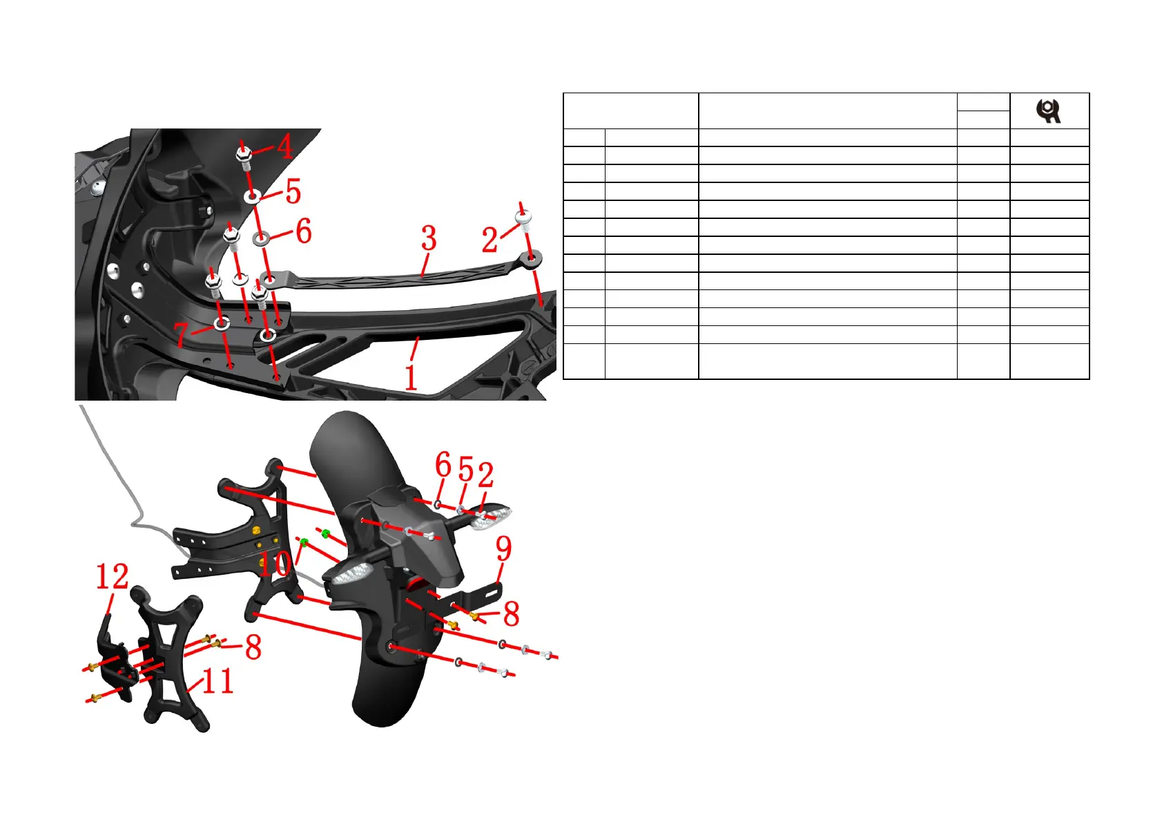
4-REAR WHELL COMPONENT
21
CHK
ADJ
NO. PART NO.
1 1020242-263021 Rear auxiliary fender aluminum alloy bracket 1
2 1251100-102000 Non-standard bolt M6×16(304 stainless steel) 5
3
1224200-090000 Rear auxiliary fender retaining plate 1
4 1250105-137093 GB5789M6×16(color zinc) 4
5 1274100-057095
Flanging bushing φ6.2×φ8.5×3.5
+
6 1244100-052000
Buffer rubber of flanging bushing
(
)
7 1250501-007093 GB93φ8(color zinc) 3
8 1251100-101000 Non-standard bolt M6×12 (304 stainless steel) 6
9 1270300-039000 HJ125-6 rear license light bracket 1
10 1250303-010093 GB6177.1M6(color zinc ) 2
11 4021200-028000 KD150-U Rear bracket for rear auxiliary mud board 1
Fig.2 REAR WHELL
COMPONENT
U rear auxiliary mud board component 2
●Retaining plate
Remove the bolt⑵ with 4# inner hexagon socket and the bolt⑷ with a 10# sleeve, remove the flange bushing
⑸ the rubber pad⑹, and finally remove the retaining plate⑶.
●Rear auxiliary mud board component
Hold the rear auxiliary mud board component,use 10#sleeve remove 3pcs bolts⑷,take off 3pcs spring washer
⑺.Take off the rear auxiliary mud board component.
Fix bolts⑻ with a 4# inner hexagon socket and remove nuts⑽ with a 10# sleeve,at the license bracket⑼ and
remove the license bracket⑼.
●Iron bracket
Hold the iron bracket component, remove 4pcs bolts⑵ fix the rear mud bosrd componet, and remove the
flange bushing⑸and rubber pad⑹.Take off the iron bracket component from the rear auxiliary mud board
component.
Using 4# inner hexagon socket remove 4pcs bolts⑻,remove the front iron bracket⑿ and the rear iron bracket
⑾.
CAUTION:
●Do not pull the cable hard when removing the sub-mud switch.
●
When reassembling, first check if there is any pressure on the wire to prevent short circuit when tightening the
bolt.
12 4024200-035000
Front segment of ZT310-V rear auxiliary clay plate
and iron bracket
1
 Loading...