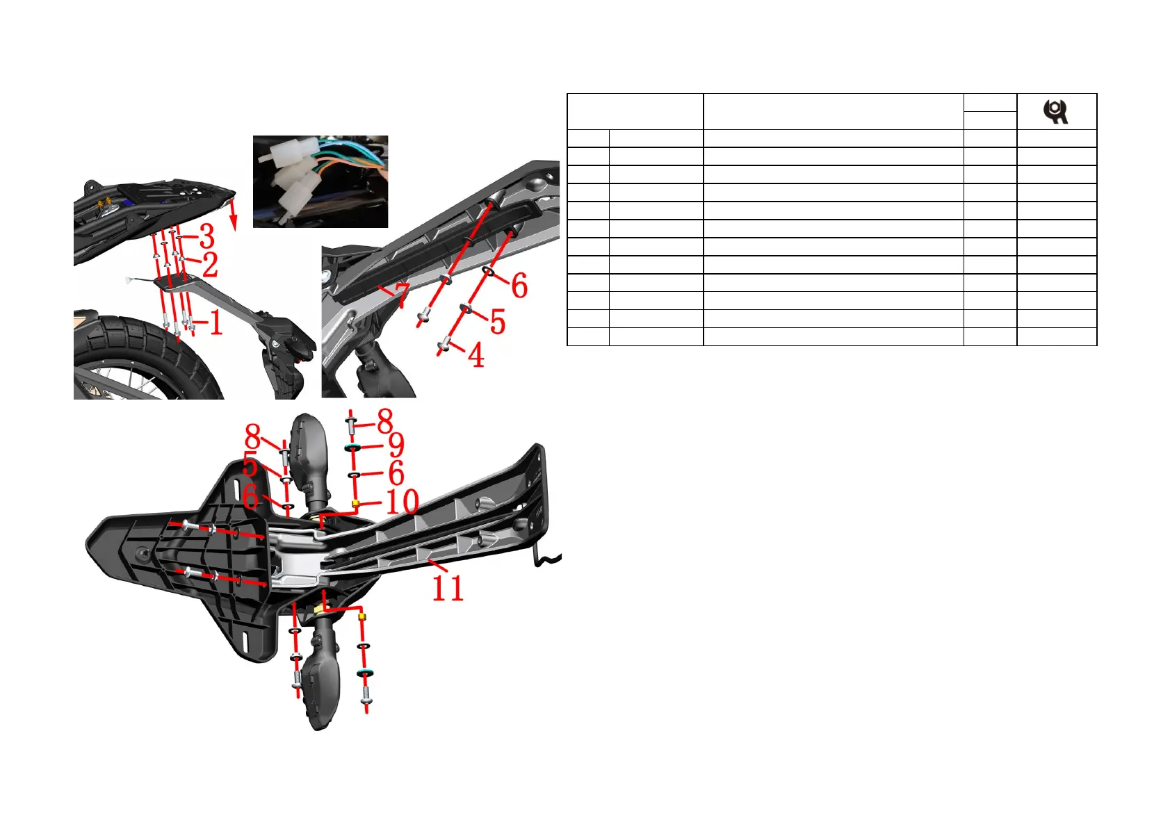
4-REAR WHELL COMPONENT
23
CHK
ADJ
NO. PART NO.
1 1250105-148093 GB5789M8×25(color zinc ) 4
2 1251700-058093
Flanging bushing φ8.2×φ11×4.5
+
3 1240300-071000 Flanging bushing rubber (φ11×φ16×1) 4
4 1251100-101000 Non-standard bolt M6×12 (304 stainless steel) 2
5 1274100-057095 Flanging bushing φ6.2×φ8.5×3.5+φ14×1.5 6
6 1244100-052000 Buffer rubber of flanging bushing (φ8.5×φ14×1) 8
7 1221200-052000
KD150-U rear fender bracket cover
8 1251100-120093 Non-standard bolts M6×16 (environmental color) 6
9 1250502-010093 GB96.1φ6(color zinc) 2
10 1274100-018000 ZT250-S anti-hot plate sleeve, muffler 2
11 4021200-045051
KD150-U rear fender bracket (dark gray matte)
U1 rear mud board component 1
●Rear mud board component
Remove the seat cushion and rear cover first.
Find the 3 plugs of the adapter cable on the left and unplug them.
Grasp the rear fender assembly and use a 12# sleeve to remove the 4 bolts (1), and remove the bushing (2) and
the cushion rubber (3).
Pull the bottom of the rear cover down for a certain distance and then pull out the adapter cable. Remove the
rear fender assembly from the bike and put it away.
●Cover
Use 4# inner hexagon to remove 2 bolts ⑷, then remove the bushing ⑸ and cushion rubber ⑹, and then
remove the cover ⑺. Pull the adapter cord plug out of the hole in the fender bracket.
●Rear fender sub-assembly
Use a 4# inner hexagon to remove the 2 bolts ⑻ at the bottom, and then remove the bushing ⑸ and cushion
rubber ⑹.
Use 4# inner hexagon to remove the bolts ⑻
on both sides of the back of the turn signal, and remove the gasket
⑼, cushion rubber ⑹ and anti-scalding board bushing ⑽.
Use a 4# inner hexagon to remove the 2 bolts ⑻
on both sides of the turn signal light-emitting surface, and then
remove the bush ⑸ and the cushion rubber ⑹.
Separate the rear mud plate sub-assembly, turn signal bracket assembly and rear mud guard bracket.
CAUTION:
●When reassembling, check if there is any pressure on the wire to prevent it from tightening.Short circuit
caused by bolts.
●Pay attention to the force when pulling out the connecetor plug.
Fig.4 REAR WHELL
COMPONENT
 Loading...