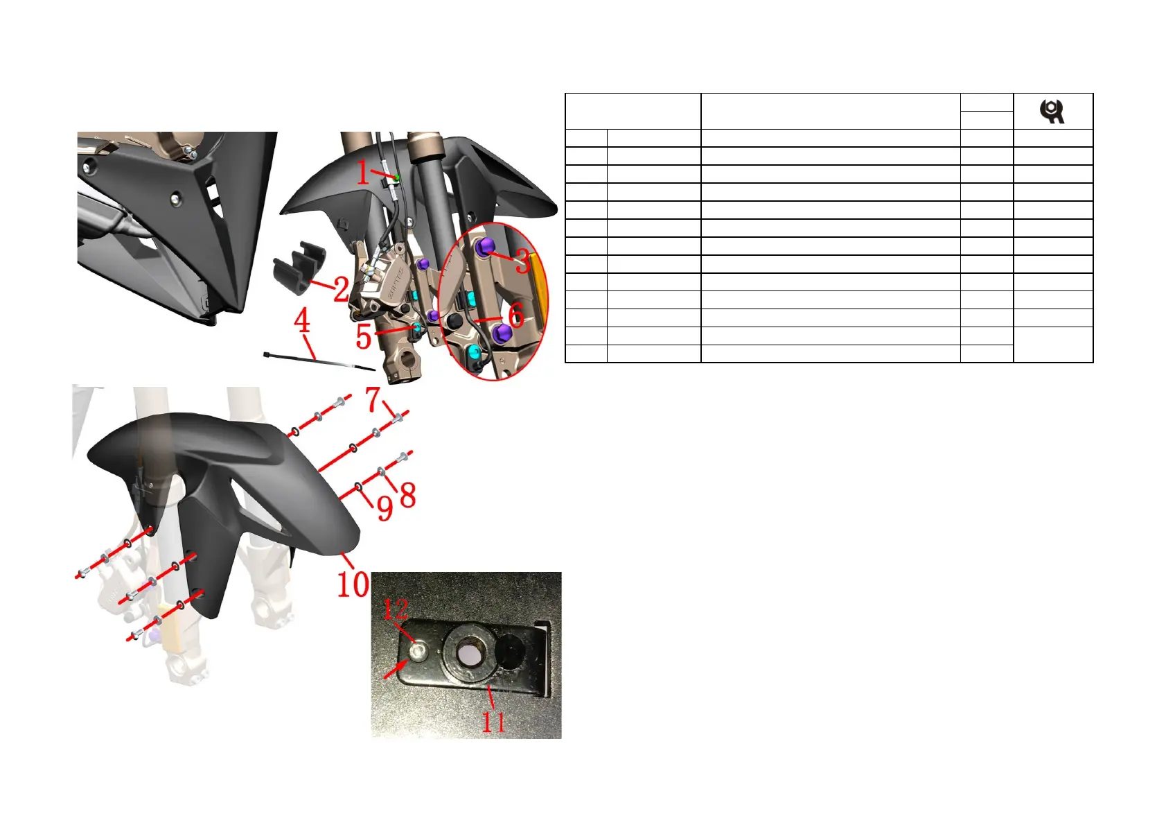
7-FRONT FORK COMPONENT
53
CHK
ADJ
NO. PART NO.
1 1251100-061093 M6×22 Hex flang bolt thread level 8.8 (color zinc) 1
2 1224100-044000 Wheel speed sensor clamp 3
3 1251100-080094 Non-standard bolt M8×37(color zinc) 2
4
1224100-037000 Grade 0 flame retardant tie (black 3.6×295) 2
5 1251100-101000 Non-standard bolt M6×12 (304 stainless steel) 1
6 1184200-045000 DF30 wheel speed sensor 1
7 1251100-102000 Non-standard bolt M6×16(304 stainless steel) 6
8 1274100-057095 Flanging bushing φ6.2×φ8.5×3.5+φ14×1.5 6
9 1244100-052000 Buffer rubber of flanging bushing (φ8.5×φ14×1) 6
10 Front mud board component 1
11 1274200-038000 ZT310-X Front fender front oil outlet pipe fixed seat 1
12 1250402-001091 GB12615 φ3×10 Rivet 1
PROCEDURE:
●Wheel speed sensor
Pull out the plug of the wheel speed sensor ⑹; then remove 3 pcs clamp⑵. Cut off the belting⑷.Using 4#
inner hexagon socket remove bolt⑸,take off the bolt⑹.
●Front disc brake caliper
Using 8# sleeve remove bolt⑴ and using 14# sleeve remove bolts⑶,so that the caliper will hang down
naturally. It is forbidden to invert the caliper toprevent the air from entering and causing the brake to fail.
●Front mud board component
Hold the front mud board componet⑽ with your hand and then remove the 6 bolts⑺ with a 4# inner hexagon
socket and remove the bushing⑻ and cushion rubber⑼.
Remove the front mudguard⑽.
The inside of the front mudguard can be protected with reticle or double-sided tape around the rivet⑿, then the
rivet⑿ is ground off with a small sander, and then the rivet⑿ and the fixing seat⑾ are removed.
CAUTION:
●
The motorcycle support should be fixed during the disassembly process to prevent accidents caused byincline.
●Disassemble the oil pipe clamp and the sensor wire clamp should pay attention to the strength.
●Pay attention to the strength when disassembling the front mud plate to prevent scratching the paint surface.
●Rivets need to be assembled with professional tools.
U front mud board & wheel speed sensor component
Fig.10 FRONT FORK
COMPONENT
after-sales
 Loading...