EasyManuals Logo
Home>ABB>Control Unit>MicroFlex e150

ABB MicroFlex e150 User Manual

ABB MicroFlex e150
180 pages
To Next Page IconTo Next Page
To Previous Page IconTo Previous Page
Page #22 background imageLoading...
Page #22 background image
22 Hardware description
Operating principle
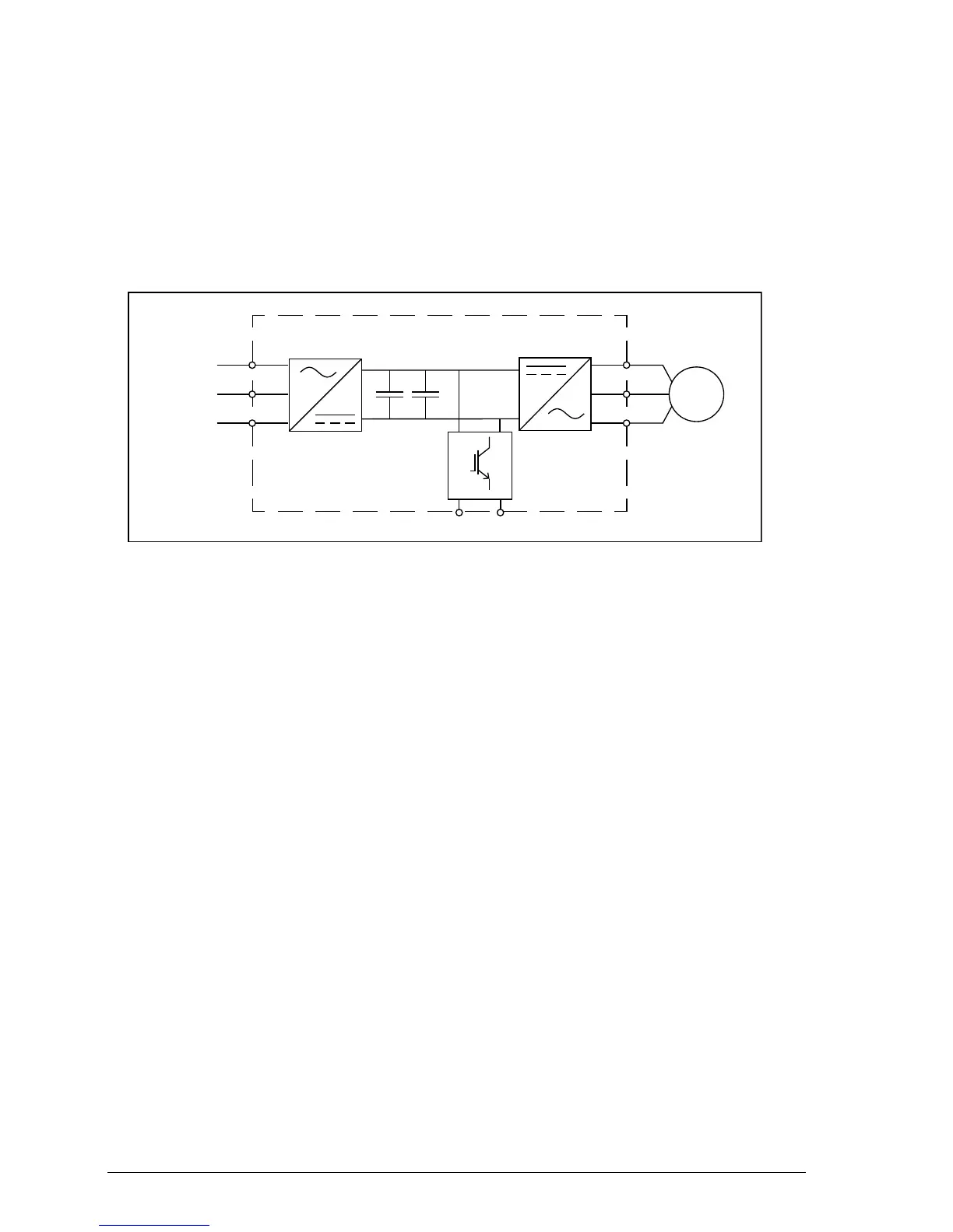
The figure below shows the simplified main circuit diagram of the drive. The rectifier
converts three-phase AC voltage to DC voltage. The capacitor bank of the
intermediate circuit stabilizes the DC voltage. The inverter converts the DC voltage
back to AC voltage for the AC motor. The brake chopper connects the external brake
resistor to the intermediate DC circuit when the voltage in the circuit exceeds its
maximum limit.
R1 R2
U
V
W
L1
L2
L3
Rectifier Capacitor
bank
Inverter
Brake chopper
AC supply
AC motor

Table of Contents

Other manuals for ABB MicroFlex e150

Questions and Answers:

Question and Answer IconNeed help?

Do you have a question about the ABB MicroFlex e150 and is the answer not in the manual?

ABB MicroFlex e150 Specifications

General IconGeneral
BrandABB
ModelMicroFlex e150
CategoryControl Unit
LanguageEnglish

Related product manuals