EasyManuals Logo
Home>ABB>Control Unit>MicroFlex e150

ABB MicroFlex e150 User Manual

ABB MicroFlex e150
180 pages
To Next Page IconTo Next Page
To Previous Page IconTo Previous Page
Page #24 background imageLoading...
Page #24 background image
24 Hardware description
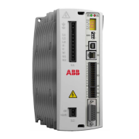
Connections - top panel
See chapter Electrical installation: AC input, motor and brake on page 43 for
installation in general.
14 Shield 7 DIN4
13 CREF1 6 DIN5
12 DIN8 5 DIN6
11 DIN9 4 DIN7
10 USRV+ 3 CREF0
9 DOUT5 2 DOUT3
8 DOUT6 1 DOUT4
OPT1: Input / Output
E1 / E2 EtherCAT®
1TX+
2TX-
3RX+
4 (NC)
5 (NC)
6RX-
7 (NC)
8 (NC)
Both connectors have
identical pinouts.
EtherCAT
IN
E2
E1
EtherCAT
OUT
E1 is also used for standard
Ethernet if DIP switch 4 is in the
ON position (see page 79).

Table of Contents

Other manuals for ABB MicroFlex e150

Questions and Answers:

Question and Answer IconNeed help?

Do you have a question about the ABB MicroFlex e150 and is the answer not in the manual?

ABB MicroFlex e150 Specifications

General IconGeneral
BrandABB
ModelMicroFlex e150
CategoryControl Unit
LanguageEnglish

Related product manuals