Electrical installation: AC input, motor and brake 45
Connecting the power cables
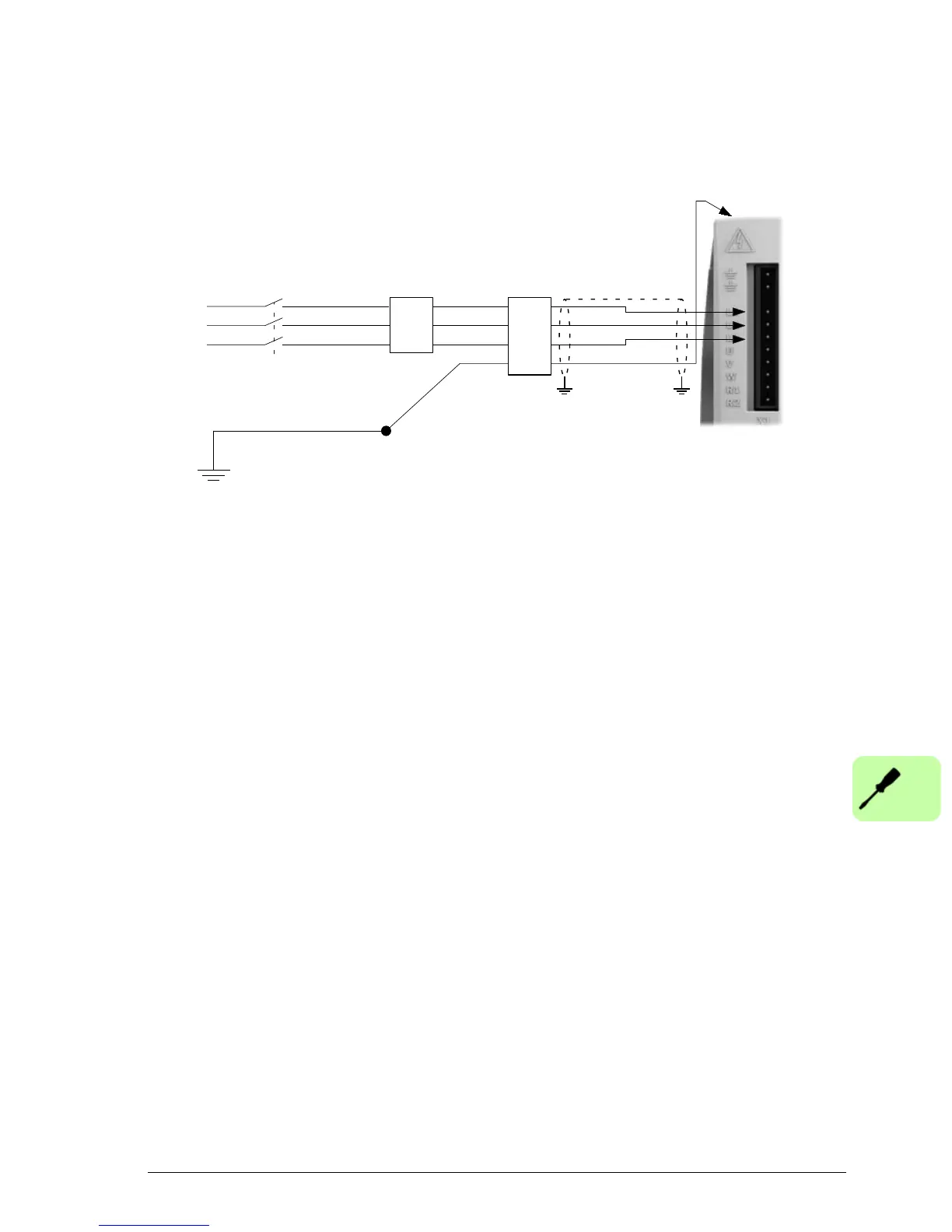
Connection diagram: AC input
MicroFlex e150 is designed to be powered from standard single or three-phase lines
that are electrically symmetrical with respect to earth/ground. The power supply
module within the MicroFlex e150 provides rectification, smoothing and current surge
protection. Fuses or circuit breakers are required in the input lines for cable
protection.
For three phase supplies, connect the supply to L1, L2 and L3 as shown above. For
single phase supplies, connect the supply and neutral to any two line inputs, for
example L1 and L2.
For CE compliance, an AC filter must be connected between the AC power supply
and the MicroFlex e150. If local codes do not specify different regulations, use at
least the same gauge wire for earth/ground as used for L1, L2 and L3.
The X1 mating connector is a Phoenix COMBICON MSTB 2,5HC/11-ST-5,08.
Tightening torque is 0.5-0.6 N·m (4.4-5.3 lb-in). The threaded hole in the top or
bottom of the case may be used as an additional functional earth/ground connection
for signals on connector X3. The threaded holes may also be used to attach shield or
strain relief clamps. The holes are threaded for M4 bolts no longer than 11 mm
(0.43 in).
Earthing / grounding
A permanent earth/ground bonding point is provided on the heat sink, which must be
used as the protective earth. It is labeled with the protective earth symbol in the
casting and does not form any other mechanical function.
Connector X1 contains earth terminals, but these must not be used as protective
earth since the connector does not guarantee earth connection first, disconnection
last. Earthing methods are shown in Typical installation example on page 41.
Route L1, L2, L3 and
earth/ground together
in conduit or cable
Circuit breaker
or fuses
AC filter
Connect
earth/ground
to protective
earth on top
of drive
To earth/ground outer shield,
use 360° clamps connected
to enclosure backplane.
STAR POINT
Isolating switch
Incoming safety
earth/ground (PE)
Line (L1)
Line (L2)
Line (L3)
AC
Supply

 Loading...