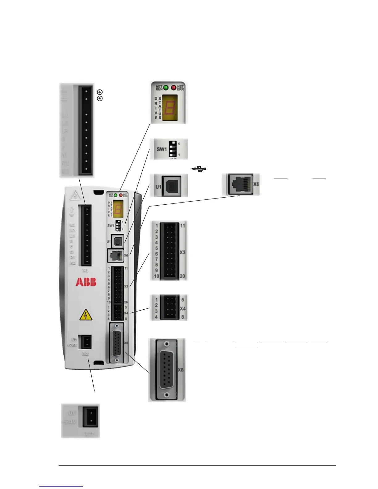
Earth/Ground
Earth/Ground
(NC)
L1 AC Phase 1/L
L2 AC Phase 2 / N
L3 AC Phase 3
UMotor U
VMotor V
WMotor W
R1 Brake
R2 Brake
The seven-segment display and the two EtherCAT
LEDs are described in MicroFlex e150 indicators on
page 119.
These switches select the Ethernet mode and
RS485 settings. See DIP switches on page 79.
1+5V
2Data-
3Data+
4GND
2-wire 4-wire
1 TXA(+)/RXA(+) TXA(+)
2 TXB(-)/RXB(-) TXB(-)
3GND GND
4 7 V out 7 V out
5 (NC) RXA(+)
6 (NC) RXB(-)
1 Status- 11 Status+
2 DOUT2- 12 DOUT2+
3 DOUT1- 13 DOUT1+
4 DIN2- 14 DIN2+
5 DIN3- 15 DIN3+
6 DIN1- 16 DIN1+
7 DIN0- 17 DIN0+
8SREF 18STO1
9SREF 19STO2
10 Shield 20 Shield
1AOUT0 5AGND
2AIN1+ 6AIN1-
3AIN0+ 7AIN0-
4 Shield 8 Shield
Pin
Incremental BiSS/SSI/ Smart Abs EnDat 2.1 SinCos
EnDat 2.2
1 CHA+ Data+ Data+ Data+ (NC)
2 CHB+ Clock+ (NC) Clock+ (NC)
3 CHZ+ (NC) (NC) (NC) (NC)
4 Sense Sense Sense Sense Sense
5 Hall U- (NC) (NC) Sin-* Sin-
6 Hall U+ (NC) (NC) Sin+* Sin+
7 Hall V- (NC) (NC) Cos-* Cos-
8 Hall V+ (NC) (NC) Cos+* Cos+
9 CHA- Data- Data- Data- (NC)
10 CHB- Clock- (NC) Clock- (NC)
11 CHZ- (NC) (NC) (NC) (NC)
12 +5 V out +5 V out +5 V out +5 V out +5 V out
13 DGND DGND DGND DGND DGND
14 Hall W- (NC) (NC) (NC) (NC)
15 Hall W+ (NC) (NC) (NC) (NC)
Shell Shield Shield Shield Shield Shield
0 V
+24V
(NC) = Not Connected. Do not
make a connection to this pin.
* EnDat v2.1 only. EnDat v2.2 does not use the Sin and Cos signals.
Tightening torque for terminal block connections X1 & X2 is 0.5-0.6 N·m (4.4-5.3 lb-in).
Maximum wire sizes: X1: 2.5 mm
2
; X3: 0.5 mm
2
.
Connector X3 is designed to accept bare wires only; do not use ferrules.
X1 Power LEDs
DIP switches
U1 USB
X6 RS485 serial port
X3 Input / Output
X4 Input / Output
X8 Feedback in
X2 Control circuit power

 Loading...