58 Electrical installation: AC input, motor and brake
Brake resistor (regeneration resistor)
An optional external brake resistor might be required to dissipate excess power from
the internal DC-bus during motor deceleration. The brake resistor must have a
resistance of at least 39 Ω, an inductance of less than 100 μH, and a minimum power
rating of 44 W. Care should be taken to select the correct resistor for the application;
see the Brake (X1) section starting on page 140. Suitable brake resistors are listed in
Resistor choice on page 143. The brake resistor output is conditionally short circuit
proof.
WARNING! Electrical shock hazard. DC-bus voltages can be present at these
terminals. Use a suitable heat sink (with fan if necessary) to cool the brake
resistor. The brake resistor and heat sink (if present) can reach temperatures in
excess of 80 °C (176 °F).
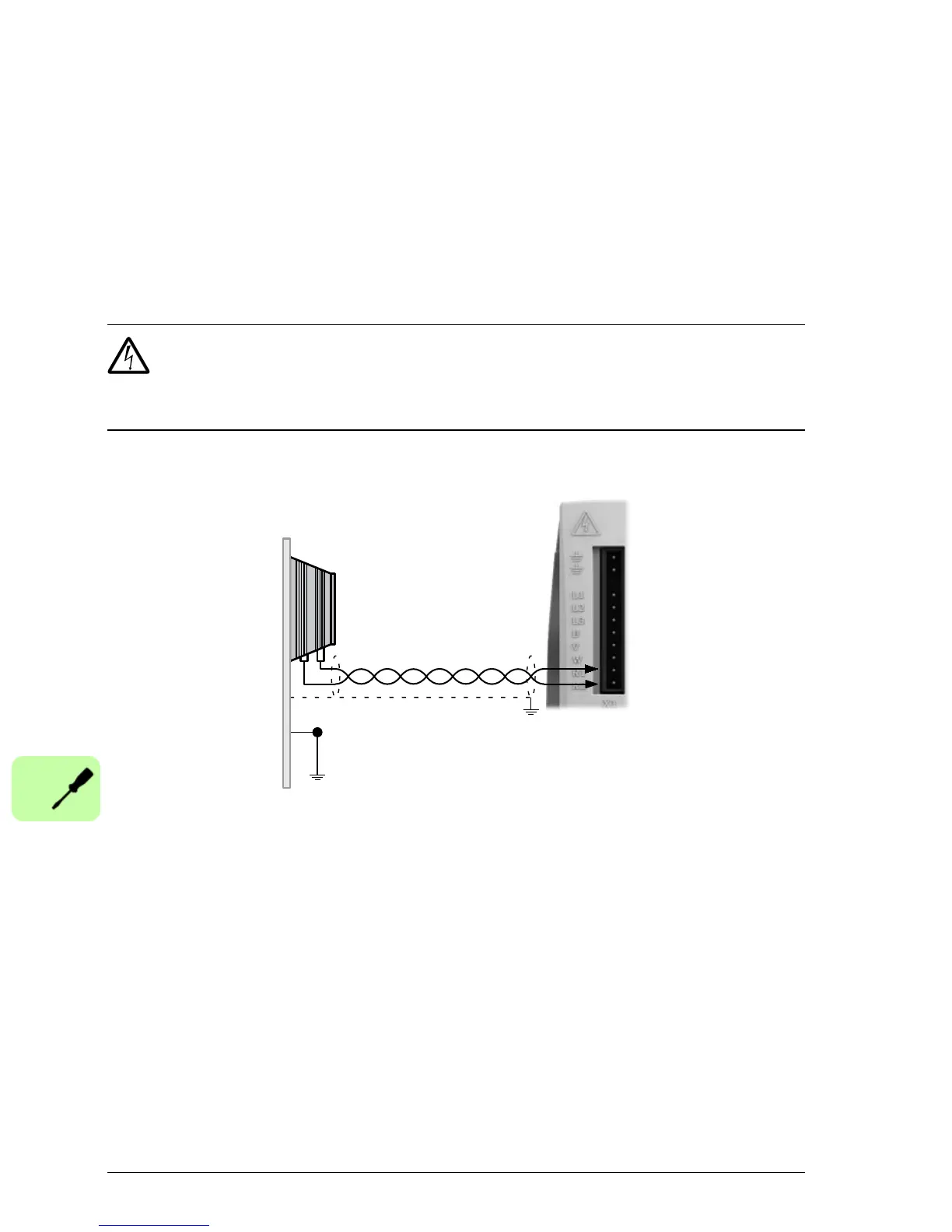
Earth/ground outer shield,
using 360° conductive
clamp connected to
enclosure backplane
Brake resistor
STAR
POINT

 Loading...