Electrical installation: input / output 81
When using BiSS, SSI, EnDat 2.2 or Smart Abs, an extra incremental encoder can be
simultaneously connected.
Twisted pairs must be used for each complementary signal pair e.g. CHA+ and CHA-
or Data+ and Data-.
The overall cable shield (screen) must be connected to the metallic shell of the D-
type connector. Connector X8 includes a ‘Sense' pin, which is used to detect the
voltage drop on long cable runs. This allows the MicroFlex e150 to increase the
encoder supply voltage on pin 12 to maintain a 5 V supply at the encoder (400 mA
max).
Incremental encoder interface
See Connection summary on page 80 for pin configuration.
The incremental encoder connections (ABZ channels and Hall signals) are made
using the 15-pin D-type female connector X8. The encoder inputs (CHA, CHB and
CHZ) accept differential signals only. The Hall inputs can be used as differential
inputs (recommended for improved noise immunity) or single ended inputs. When
used as single ended inputs, leave the Hall U-, Hall V- and Hall W- pins unconnected.
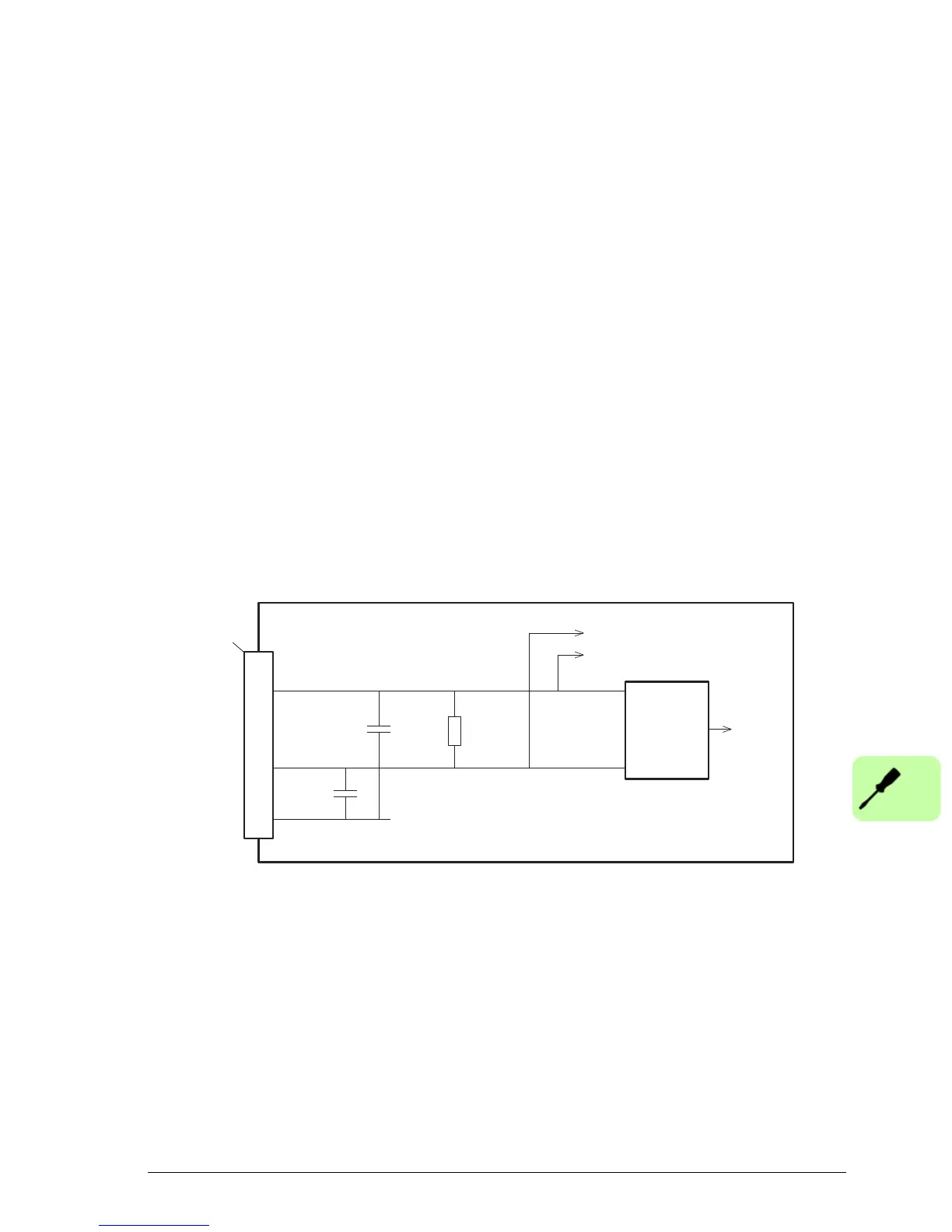
Encoder channel input circuit - channel A shown:
MicroFlex e150
CHA+
CHA-
1
9
13
DGND
120R
to CPU
X8
to encoder signal loss detection
MAX3096
Differential
line receiver

 Loading...