Electrical installation: AC input, motor and brake 51
24 V control circuit supply
A 24 V DC supply must be provided to power the controlling electronics. This is
useful for safety reasons where AC power is removed from the power stage, but the
controlling electronics must remain powered to retain position and I/O information.
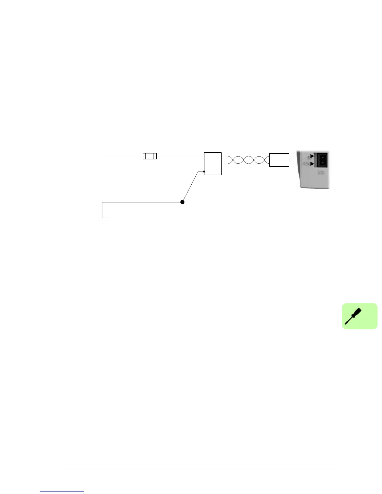
A separate fused 24 V supply should be provided for the MicroFlex e150. If other
devices are powered from the same 24 V supply, a filter (part FI0014A00) should be
installed to isolate the MicroFlex e150 from the rest of the system. Alternatively, a
ferrite sleeve can be attached to the supply cable near connector X2.
24 V filter
(optional)
Use a twisted pair cable,
with ferrite sleeve attached
close to connector X2.
Ferrite
sleeve**
STAR
POINT
Incoming safety
earth/ground (PE)
Customer supplied
24 V DC
Fuse *
* Recommended fuse: Bussman S504 20 x 5 mm anti-surge 2 A.
** Recommended ferrite sleeve: Fair-Rite part 0431164281 or similar.
X2
+24 V
GND

 Loading...