4
ALC
5
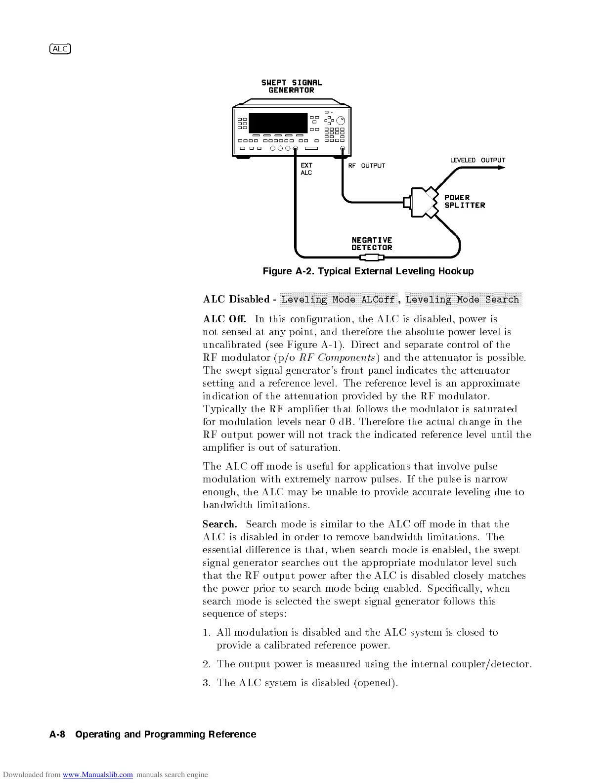
Figure A-2. Typical External Leveling Hookup
ALC Disabled -
NNNNNNNNNNNNNNNNNNNNNNNNNNNNNNNNNNNNNNNNNNNNNNNNNNNNNNNNNNNNNN
Leveling Mode ALCoff
,
NNNNNNNNNNNNNNNNNNNNNNNNNNNNNNNNNNNNNNNNNNNNNNNNNNNNNNNNNNNNNN
Leveling Mode Search
ALC O.
In this conguration, the ALC is disabled, po
wer is
not sensed at any p oint, and therefore the absolute p ower level is
uncalibrated (see Figure A-1). Direct and separate con
trol of the
RF mo dulator (p/o
RF Components
) and the attenuator is possible.
The swept signal generator's front panel indicates the attenuator
setting and a reference level. The reference level is an approximate
indication of the attenuation provided by the RF mo dulator.
Typically the RF amplier that follows the mo dulator is saturated
for mo dulation levels near 0 dB. Therefore the actual c
hange in the
RF output p ower will not track the indicated reference level until the
amplier is out of saturation.
The ALC o mo de is useful for applications that in
volve pulse
mo dulation with extremely narrow pulses. If the pulse is narrow
enough, the ALC may b e unable to provide accurate leveling due to
bandwidth limitations.
Search.
Search mo de is similar to the ALC o mo de in that the
ALC is disabled in order to remove bandwidth limitations. The
essential dierence is that, when search mo de is enabled, the swept
signal generator searches out the appropriate mo dulator level such
that the RF output power after the ALC is disabled closely matches
the power prior to search mo de being enabled. Specically, when
search mo de is selected the swept signal generator follo ws this
sequence of steps:
1. All mo dulation is disabled and the ALC system is closed to
provide a calibrated reference p ower.
2. The output power is measured using the internal coupler/detector.
3. The ALC system is disabled (op ened).
A-8 Operating and Programming Reference

 Loading...


