Modulation
Modulation
General Circuit Theory
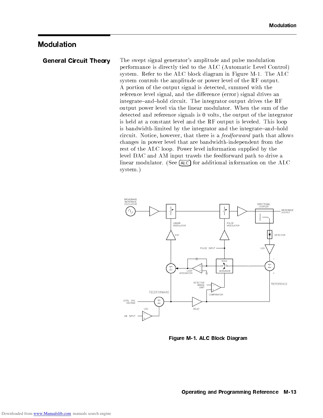
The swept signal generator's amplitude and pulse mo dulation
performance is directly tied to the ALC (Automatic Level Control)
system. Refer to the ALC blo ck diagram in Figure M-1. The ALC
system controls the amplitude or p ower level of the RF output.
A portion of the output signal is detected, summed with the
reference level signal, and the dierence (error) signal drives an
integrate{and{hold circuit. The integrator output drives the RF
output p ower level via the linear mo dulator. When the sum of the
detected and reference signals is 0 volts, the output of the integrator
is held at a constant level and the RF output is leveled. This lo op
is bandwidth-limited by the integrator and the integrate{and{hold
circuit. Notice, however, that there is a
feedforward
path that allo ws
changes in power level that are bandwidth-independent from the
rest of the ALC lo op. Power level information supplied by the
level DAC and AM input travels the feedforward path to drivea
linear mo dulator. (See
4
ALC
5
for additional information on the ALC
system.)
Figure M-1. ALC Block Diagram
Operating and Programming Reference M-13

 Loading...


