NNNNNNNNNNNNNNNNNNNNNNNNNNNNNNNNNNNNNNNNNNNNNNNNNNNNNN
Step Control Master
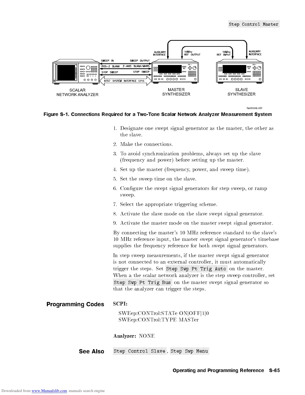
Figure S-1. Connections Required for a Two-Tone Scalar Network Analyzer Measurement System
1. Designate one swept signal generator as the master, the other as
the slave.
2. Make the connections.
3. Toavoid synchronization problems, always set up the slave
(frequency and power) b efore setting up the master.
4. Set up the master (frequency,power, and sweep time).
5. Set the sweep time on the slave.
6. Congure the swept signal generators for step sweep, or ramp
sweep.
7. Select the appropriate triggering scheme.
8. Activate the slave mo de on the slaveswept signal generator.
9. Activate the master mo de on the master sw
ept signal generator.
By connecting the master's 10 MHz reference standard to the sla
ve's
10 MHz reference input, the master swept signal generator's timebase
supplies the frequency reference for b oth swept signal generators.
In step sweep measurements, if the master swept signal generator
is not connected to an external controller, it must automatically
trigger the steps. Set
NNNNNNNNNNNNNNNNNNNNNNNNNNNNNNNNNNNNNNNNNNNNNNNNNNNNNNNNNNNNNNNNN
Step Swp Pt Trig Auto
on the master.
When a the scalar network analyzer is the step sweep controller, set
NNNNNNNNNNNNNNNNNNNNNNNNNNNNNNNNNNNNNNNNNNNNNNNNNNNNNNNNNNNNNN
Step Swp Pt Trig Bus
on the master swept signal generator so
that the analyzer can trigger the steps.
Programming Codes
SCPI:
SWEep:CONTrol:STATeON
j
OFF
j
1
j
0
SWEep:CONTrol:TYPE MASTer
Analyzer:
NONE
See Also
NNNNNNNNNNNNNNNNNNNNNNNNNNNNNNNNNNNNNNNNNNNNNNNNNNNNNNNN
Step Control Slave
,
NNNNNNNNNNNNNNNNNNNNNNNNNNNNNNNNNNNNNNNNN
Step Swp Menu
Operating and Programming Reference S-65

 Loading...


