14 Rockwell Automation Publication 1783-UM003G-EN-P - December 2012
Chapter 1 Getting Started
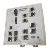
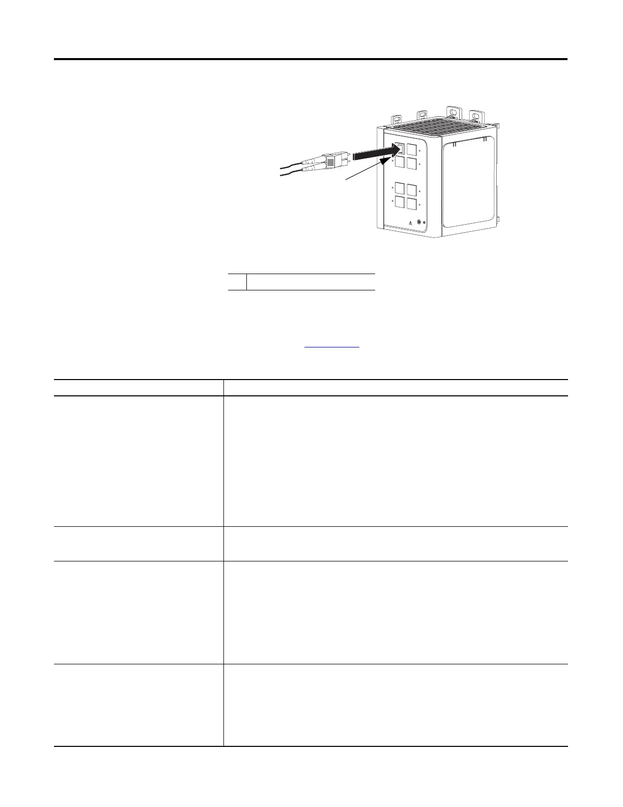
Figure 3 - 1783-MX08F Switch Fiber Expansion Module
Hardware Features
These features are common to both the Stratix 8000 and Stratix 8300 switches.
See the figures on pages 13…14
for an illustration of these features.
1 100BASE-FX ports
Hardware Features
Feature Description
Power and relay connector You connect the DC power and alarm signals to the switch through two front panel connectors. One
connector provides primary DC power (supply A) and the major alarm signal, and a second connector
(supply B) provides secondary power and the minor alarm signal. The two connectors are physically
identical and are in the upper left side of the front panel.
The switch can operate with a single power source or with dual power sources. When both power
sources are operational, the switch draws power from the DC source with the higher voltage. If one of
the two power sources fail, the other continues to power the switch.
The power and relay connectors also provide an interface for two independent alarm relays: the major
alarm and the minor alarm. The relays can be activated for environmental, power supply, and port
status alarm conditions and can be configured to indicate an alarm with either open or closed
contacts. The relay itself is normally open, so under power failure conditions, the contacts are open.
From the Command Line Interface (CLI), you can associate any alarm condition with one alarm relay or
with both relays.
Console port For configuring, monitoring, and managing the switch, you can connect a switch to a computer through
the console port and the supplied RJ45-to-DB-9 adapter cable. If you want to connect a switch to a
terminal, you need to provide an RJ45-to-DB-25 female DTE adapter.
Dual-purpose uplink ports The two dual-purpose uplink ports may each be configured for RJ45 (copper) or SFP (fiber) media
types. Only one of these connections in each of the dual-purpose ports can be active at a time. If both
ports are connected, the SFP module port has priority.
You can set the copper RJ45 ports to operate at 10, 100, or 1000 Mbps, Full-duplex or Half-duplex. You
can configure them as fixed 10, 100, or 1000 Mbps (Gigabit) Ethernet ports and can configure the
duplex setting.
You can use approved Gigabit (or 100 Mbps) Ethernet SFP modules to establish fiber-optic connections
to other switches. These transceiver modules are field-replaceable, providing the uplink interfaces
when inserted in an SFP module slot. You use fiber-optic cables with LC connectors to connect to a
fiber-optic SFP module. These ports operate Full-duplex only.
10/100 ports You can set the 10/100 ports to operate at 10 or 100 Mbps, Full-duplex or Half-duplex You can also set
these ports for speed and duplex autonegotiation in compliance with IEEE 802.3-2002. (The default
setting is autonegotiate.)
When set for autonegotiation, the port senses the speed and duplex settings of the attached device. If
the connected device also supports autonegotiation, the switch port negotiates the best connection
(that is, the fastest line speed that both devices support and Full-duplex transmission if the attached
device supports it) and configures itself accordingly. In all cases, the attached device must be within
100 m (328 ft) of the switch.
 Loading...


