1-59
Cisco ASA Series CLI Configuration Guide
Chapter 1 Configuring a Cluster of ASAs
Configuration Examples for ASA Clustering
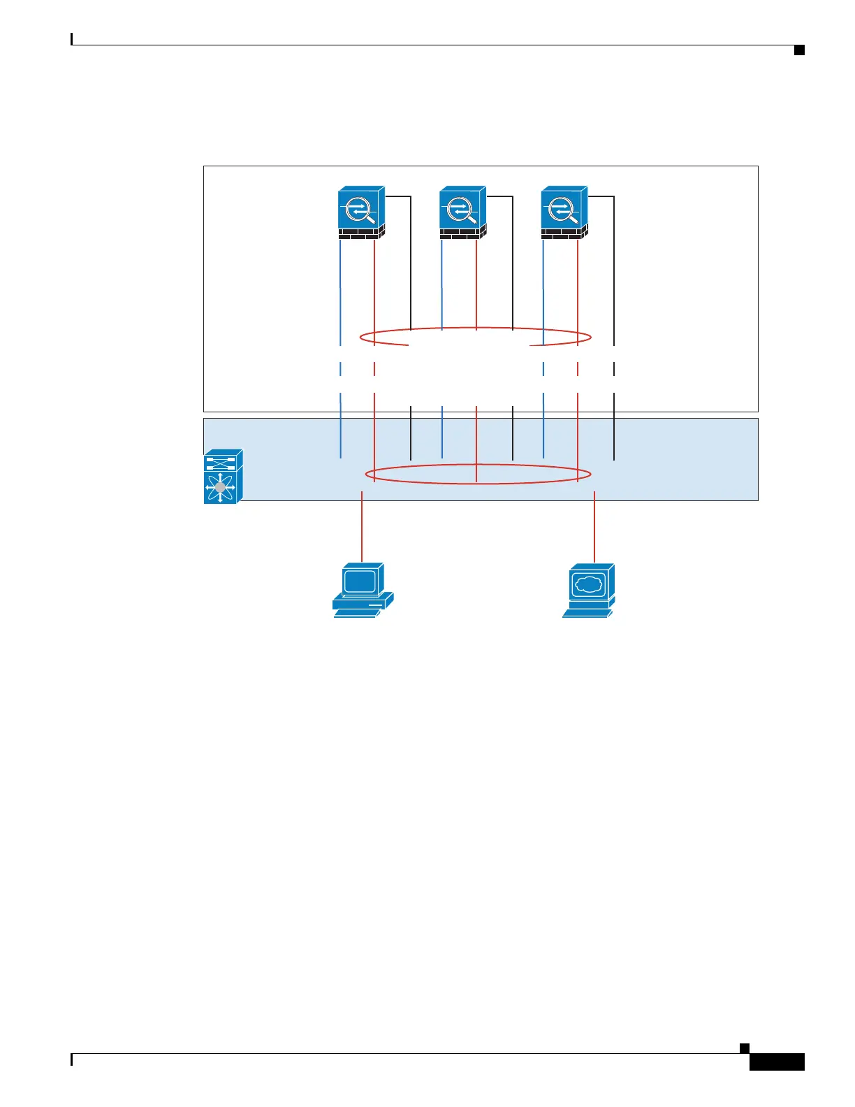
Firewall on a Stick
Data traffic from different security domains are associated with different VLANs, for example,
VLAN 10 for the inside network and VLAN 20 for the outside network. Each ASA has a single physical
port connected to the external switch or router. Trunking is enabled so that all packets on the physical
link are 802.1q encapsulated. The ASA is the firewall between VLAN 10 and VLAN 20.
When using Spanned EtherChannels, all data links are grouped into one EtherChannel on the switch side.
If an ASA becomes unavailable, the switch will rebalance traffic between the remaining units.
Interface Mode on Each Unit
cluster interface-mode spanned force
ASA1 Master Bootstrap Configuration
interface tengigabitethernet 0/8
no shutdown
description CCL
cluster group cluster1
local-unit asa1
cluster-interface tengigabitethernet0/8 ip 192.168.1.1 255.255.255.0
priority 1
key chuntheunavoidable
enable noconfirm
ASA1
333221
ten0/8
ten0/9
man0/0
ASA2
ten0/8
ten0/9
man0/0
ASA3
ten0/8
ten0/9
man0/0
Switch
management
10.1.1.1/24 (Pool: .2-.9),
2001:DB8::1002/64
(Pool: 8 IPs)
Cluster Control Link
192.168.1.1, .2, and .3
port-ch5
VLAN 10, VLAN 20 Trunk
VLAN 10
VLAN 20
Client
Server
port-ch1 Spanned
port-ch1.10 inside VLAN 10 10.10.10.5/24, 2001:DB8:2::5/64
MAC: 000C.F142.4CDE
port-ch1.20 outside VLAN 20 209.165.201.5/27, 2001:DB8:2::5/64
MAC: 000C.F142.5CDE
 Loading...