Chapter 5. Diagnostics
167
L
O
C
Y
E
L
C
G
A
F
R
M
B
7
B
P
V
0
-
D
E
N
A
I
S
L
P
R
X
L
P
T
X
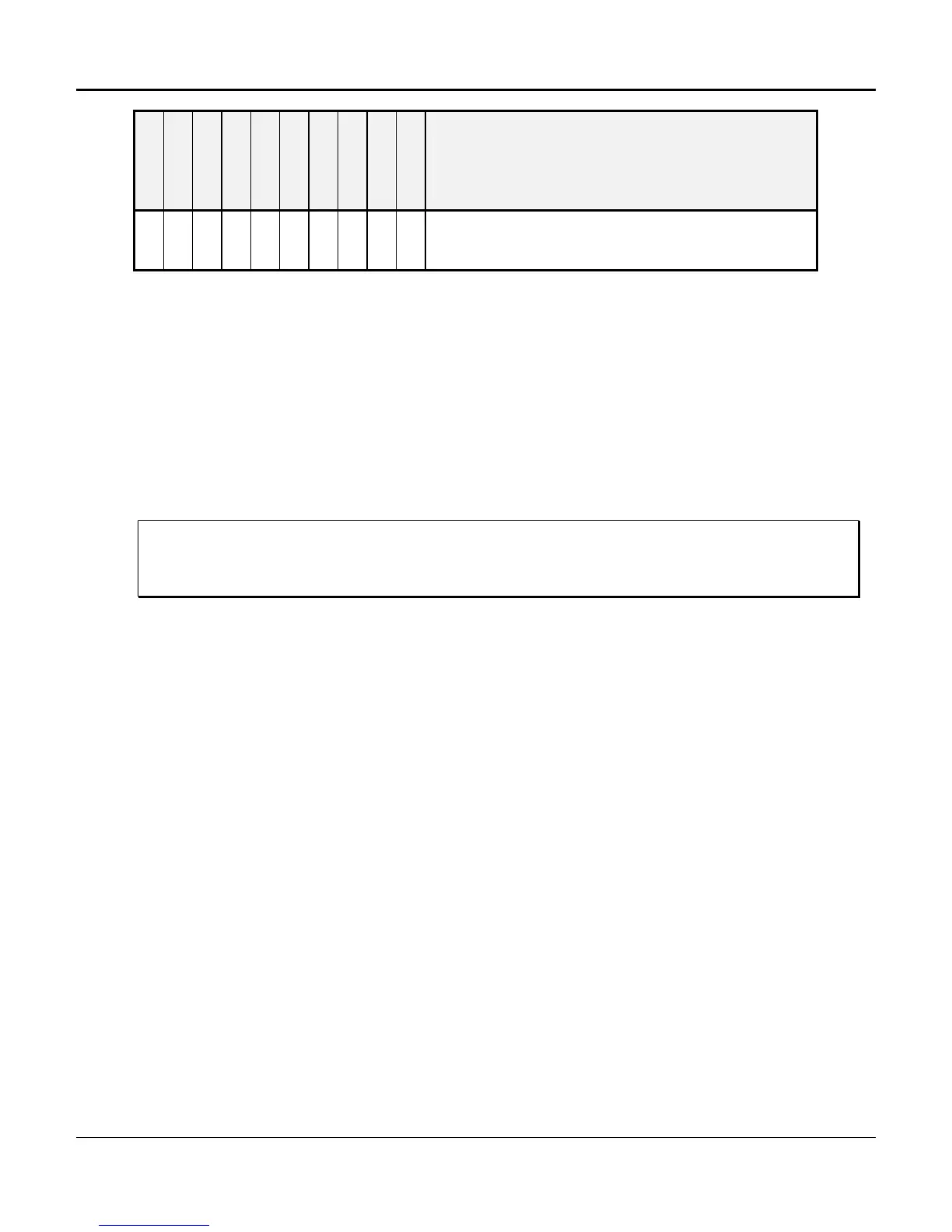
POSSIBLE PROBLEMS / SOLUTIONS
Y Y Remote end detects problem; may be transmit failure.
Put a loopback on T1 interface to clear alarms. If alarms
clear, distant-end T1 span has a problem.
System-Level Troubleshooting
If a T1 failure occurs, loop the T1 at the backplane connector by performing the following steps.
This will isolate the problem to either the D/I Mux III system, or to another part of the network.
1. Remove the T1 cable from the T1-1 connector.
2. Install the RJ-48 loopback plug (packed with the shelf in the bag kit) into the T1-1 RJ-48
connector. (Refer to Figure 5-1 or 5-2 for information on building a loopback plug.)
3. If the D/I Mux III system “times out” (if the alarm clears) within 20 seconds with the loopback
connector installed, the failure is elsewhere in the network. (It may be necessary to place
the shelf in local internal timing to force the shelf to acquire timing.)
Note: Placing the loopback plug in the T1-1 connector will affect the alarm lights on
the T1-2 LIU. If optioned for drop-and-insert operation, the alarms do not
clear.
4. Remove the second T1 cable from the T1-2 connector.
5. Move the loopback plug from T1-1 to the T1-2 connector, and note the readings on the T1-2
LIU.
If the D/I Mux III remains in alarm, go to "Board-Level Troubleshooting."
Board-Level Troubleshooting
Perform the following procedures after a failure has been isolated to the D/I Mux III system.
Failures affecting all channels are usually in the common equipment units. Typical common
equipment failures are indicated by the LIU front panel LEDs, and/or loss of data or signaling
transmission on all channels in one or both directions. Failures affecting a single channel are
usually caused by a faulty line card, or by a fault in the strobe board. Before replacing individual
units, check the following.
1. Ensure that the common equipment and line cards are fully seated in the system backplane
card edge connectors.
2. Ensure that all connector cables are fully seated.
3. Turn power to the shelf OFF then ON. This will re-initialize the D/I Mux III system
configuration. See if this clears the problem.
4. Measure the -48 V DC on the D/I Mux III shelf at the terminal block, TB1 pin 1 (referenced to
TB1 pin 2 battery ground). The D/I Mux III shelf operates from -44 V DC to -56 V DC.
5. If your system is -24 VDC then measure the -24 V DC on the D/I Mux III shelf at the terminal
block, TB1 pin 1 (referenced to TB1 pin 2 battery ground). The D/I Mux III shelf operates
from -22 V DC to -28 V DC.

 Loading...