Chapter 1. System Overview and Modes of Operation
7
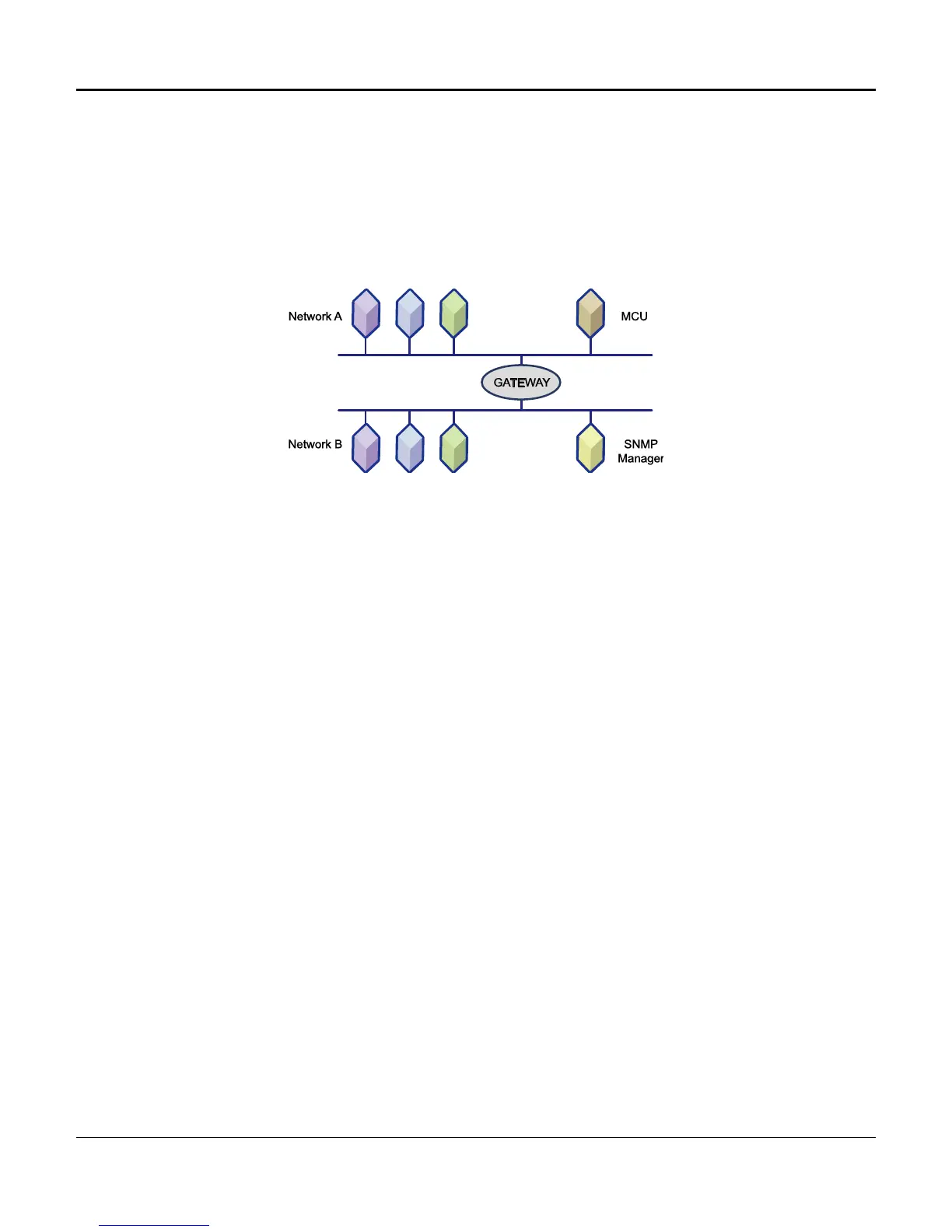
Gateway
The AMCU makes special provision for the case where it is connected to a network that is linked to other
networks by a Gateway (special router). In this case, messages to the manager must be addressed to
pass through the Gateway, and the address of the Gateway must be known to the AMCU. If the AMCU
is configured with a “default Gateway address,” messages to SNMP managers with IP Addresses not on
the same network as the AMCU will not be properly addressed and forwarded by the indicated Gateway.
Figure 1-6 depicts a typical Gateway connection across two networks with different IP Addresses.
Figure 1-6. Gateway Connection
Transmission Control
T1 equipment operates at 1.544 Mbps, which is the product of the twenty-four 64 Kbps channels, plus 8
Kbps for overhead. This is known as the DS-1 rate and a T1 facility is known as a DS-1 facility. The
common (inter-exchange) carriers (e.g., AT&T, MCI, SPRINT, etc.) divide the DS-1 signal into the 24 64-
Kbps DS0 channels, using this signal rate as a standard digital communications interconnection method
within North America. Local Exchange carriers, such as Pacific Bell and Southwest Bell, etc., also offer
this service for private networks.
The T1 signal is based upon what are known as DS1 Frame, and DS1 Extended Super Frame (ESF).
Simply defined, the DS 1 ESF scheme is as follows:
• DS0 Data Signal - Unframed, continuous bit stream, at a rate of 64 Kbps
• DS0 Octet - Eight consecutive bit portions comprising DS0 data signal
• DS1 Frame - Twenty-four DS0 octets, preceded by one framing bit
• DS1 ESF - Twenty-four consecutive DS1 frames
• DS1 Data Signal - Continuous stream of DS1 frames, at the standard DS1 data rate of 1.544 Mbps
The DS1 signal consists of 24 time slots, each of which transmits and/or receives one DS0 within the
multiplexer. Some external signals are capable of more or less than one DS0, in which case several
DS0s might be required for one type of signal, while in other cases several signals might occupy just one
DS0. This determination is based upon the application, and number of channel cards included in the
system. DS0 time slots are user-configurable. Installing a channel card does not automatically assign
its transmission path. Time slots and physical card slots are independent of one another, and the
transmission path must be mapped.

 Loading...