Chapter 3. Installation
74
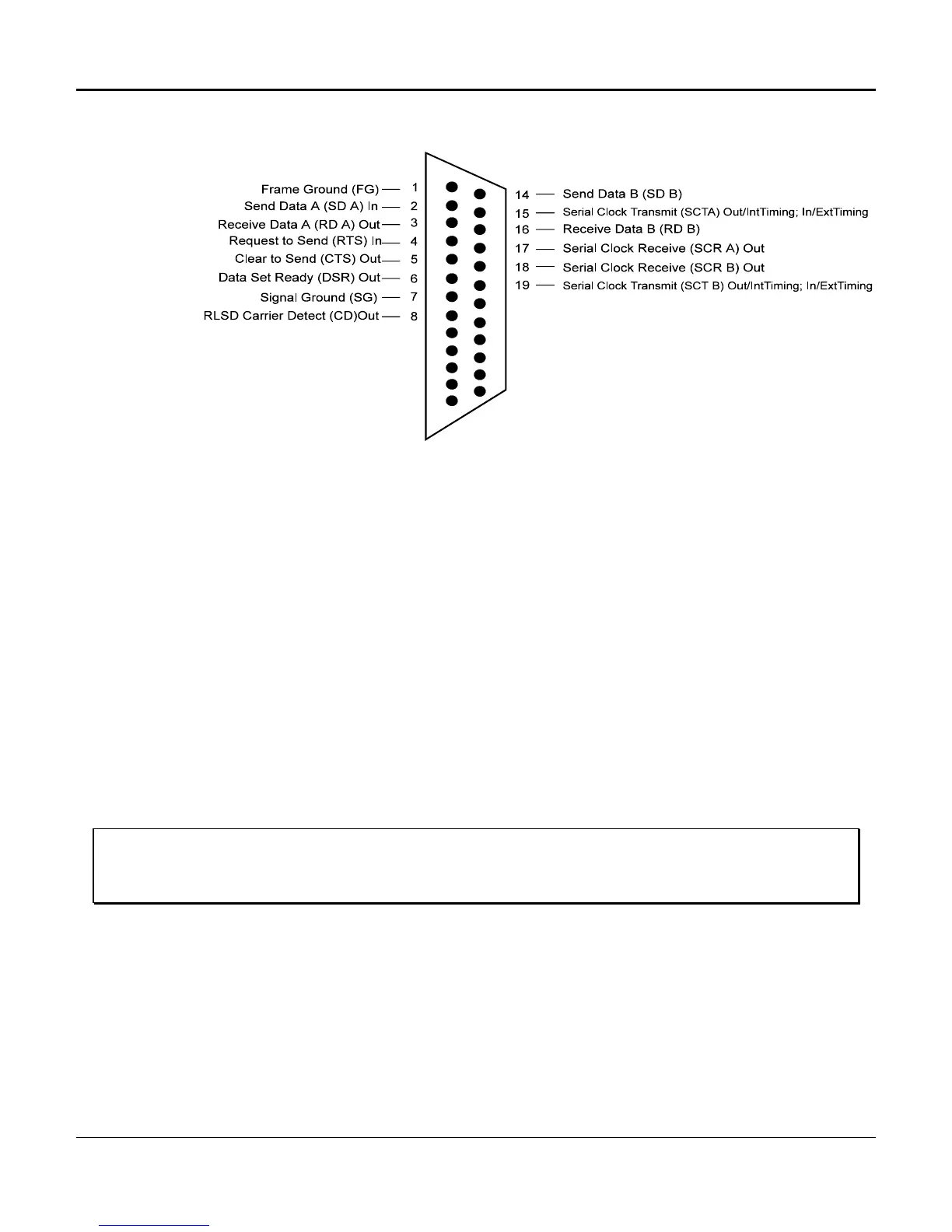
Figure 3-20. V.35 Female Data Circuit
Digital Program Channels
Digital Program Channels (DPCs) can use the 50-pin voice connectors or the DB-25 connectors.
They connect to Tip and Ring for transmit, and Tip 1 and Ring 1 for receive.
Common Equipment and Line Card Installation
All common equipment and line cards are installed in the same manner. Common equipment units
should be installed before line cards, and must be placed in the correct common equipment card slot, as
designated on the static strip. Line cards can be placed in any line card slot of the multiplexer. See the
D/I Mux III front view diagrams in Figures 3-15, 3-16 and 3-17 for the location of the various card slots,
and follow the order given in this chapter for common equipment installation. (See Appendix F. Shelf
Supplement, for details on older model shelves.)
Warning!
Power down the shelf when installing or replacing common equipment. Check the static strip in the shelf to
ensure that the card being installed is the correct card for that slot, or damage can result.
Electrostatic Precautions
Precaution must be taken to prevent electrostatic damage to plug-in units. Electrostatic damage
can cause semiconductors and other static-sensitive components to fail, resulting in
unexplainable test failures and degraded performance.

 Loading...