Chapter 1. System Overview and Modes of Operation
26
AMCU Sub-Board Circuit Description
The AMCU sub-board interfaces to the AMCU motherboard via a 20-pin connector, and includes
the hardware that supports SNMP. A full TCP/IP communication protocol stack allows SNMP
and Telnet to communicate with a centrally located Network Operations Center (NOC). A
network manager uses automated tools (for example, to read or compile a Management
Information Base, or MIB) to manage distributed node devices, including D/I Mux III multiplexers.
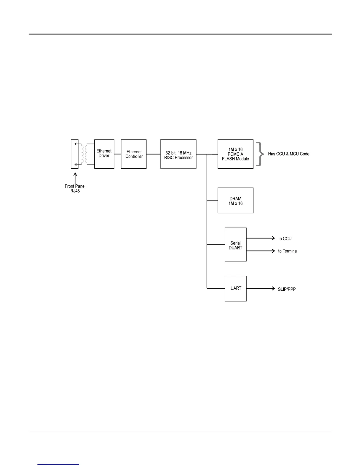
See Figure 1-12 for a detailed AMCU sub-board block diagram.
Figure 1-12. AMCU Sub-board Circuit Flow Block Diagram
The following section lists and describes the various elements and components comprising the
AMCU sub-board circuit.

 Loading...