Chapter 1. System Overview and Modes of Operation
15
COMPONENT OVERVIEW
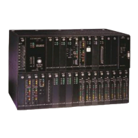
The Coastcom D/I Mux III multiplexer incorporates a modular design that is cost effective in meeting
specific applications, and requiring purchase of only what is needed. Modular system components are
easily added or removed as network requirements change, also simplifying maintenance.
There are three main system components to a D/I Mux III multiplexer: the shelf, the common equipment
units, and the line cards. It takes all three of these elements to make a complete D/I Mux III.
The shelf is the housing for the modular common control units and line cards. The shelf has a
multilayered backplane with card edge connectors inside to receive the various modules. On the back of
the shelf (backplane) are wiring connections for voice circuits, data circuits, T1 circuits, power, and
synchronization.
Common equipment units are the essentials of every multiplexer. They control the system, perform the
multiplexing function, and interface to the T1 transmission lines. A D/I Mux III must have either a
Common Control Unit (CCU) or an Advanced Multiplexer Control Unit (AMCU), two Line Interface Units
(LIUs), a Dual DSX-1 or Dual CSU Interface, Strobe cards (upper and lower strobe cards for the 24-slot
shelf), and a power supply. These are the units common to every system, and they reside in specific
shelf card slots.
Line cards offer application-specific circuits to the user. They include voice, data, and special services.
Unless otherwise specified, a line card can be installed in any shelf line card slot. The circuits from the
line cards are multiplexed into the T1 transmission signal through the common equipment and shelf
backplane. Figure 1-7 depicts a simple D/I Mux III system in block diagram.

 Loading...