Chapter 3 Wiring ASDA-A2R Series
Revision December, 2014
3-55
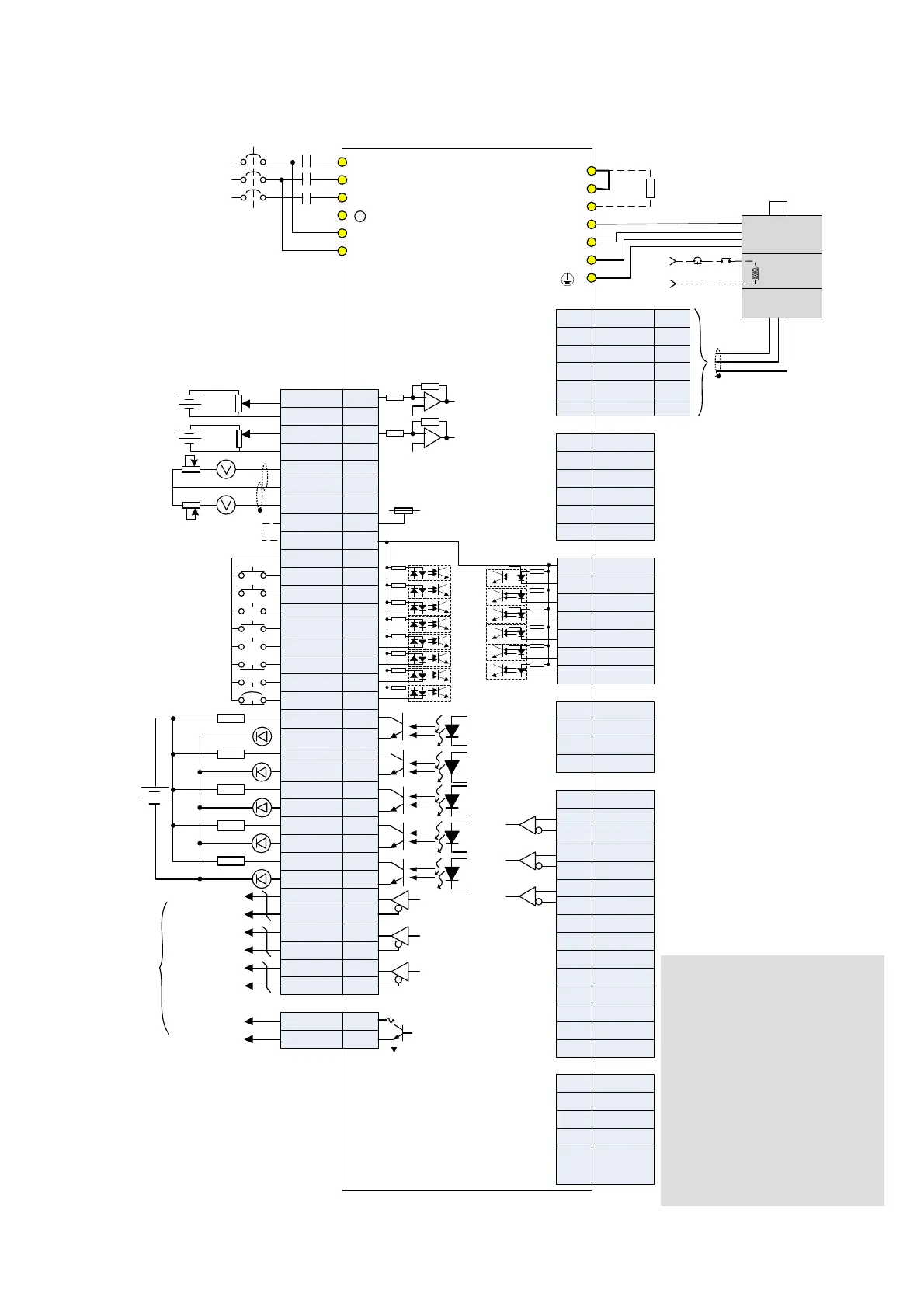
3.10.3 Speed Mode Standard Wiring
OCZ
GND
48
13
VDD
MON1
GND
MON2
COM+
COM-
DI1
DI2
DI3
DI4
DI5
DI6
DI7
DI8
DO1+
DO2-
DO3-
DO4-
DO2+
DO3+
DO4+
DO5+
DO1-
DO5-
/OA
OA
OB
/OB
/OZ
OZ
12,13,19
45,47,49
T-REF
GND
15
17
11
9
10
34
8
33
32
30
7
6
5
4
3
1
2
26
28
31
21
22
24
50
27
25
23
RS485+
RS232_RX
RS232_TX
GND
RS485-
-
5
6
4
3
1
2
7
5
6
4
3
1
2
COM+
EDI9-
EDI10-
EDI11-
EDI12-
EDI13-
EDI14-
+5V DC
Data-
Data+
GND
4
3
1
2
CN3
CN7
CN4
CN5
CN6 CANopen
4KΩ
4KΩ
4KΩ
4KΩ
4KΩ
4KΩ
4KΩ
4KΩ
Max. output current: 50mA
Voltage: 30V
SON
TRQLM
SPD0
SPD1
ARST
CWL
CCWL
EMGS
1.5KΩ
1.5KΩ
1.5KΩ
1.5KΩ
1.5KΩ
SRDY
ZSPD
BRKR
TSPD
ALRM
24V
A phase
differential signal
B phase
differential signal
Z phase
differential signal
Z phase signal
(open-collector)
Encoder
pulse
output
10KΩ
10KΩ
Shielded twisted-
pair cable
10KΩ
±10V
10KΩ
DC 24V
SG
*1
*5
*4
1,9
3,11
2,10
7,15
CAN H
CAN L
CAN GND
-
CAN GND
4,12
5,13
6,14
8,16
Opt A
+5V
Opt B
Opt /B
Opt /A
Opt Z
Opt /Z
GND
GND
9
7
5
6
3
1
2
8
4
-
HALL_U
12
10
11 HALL_V
HALL_W
-
-
-
TEMP+
TEMP-
13
14
15
4KΩ
4KΩ
4KΩ
4KΩ
4KΩ
4KΩ
42
44
18
13
16
T+
T-
-
+5V
-
GND
4
7
13,15
14,16
9
5
CN2
CN1
Blue
Blue /
Black
Green
Black
Red
Green /
Black
P⊕
D
C
U
V
W
R
S
T
L1c
L2c
MC
MCCB
AC 200/230 V
3-phase
50/60Hz
Servo Drive
ASDA-A2R series
10KΩ
Regenerative
resistor
Red
white
Black
Green
SG
Brake
Power
Encoder
BRKREMGS
24V
Shielded twisted-
pair cable
GND
V-REF
10KΩ
10KΩ
10KΩ
±10V
*6
*3
*2
Note:
*1: Please refer to section 3.3.3 for
the wiring of C9~C12 SINK /
SOURCE mode.
*2: No built-in regenerative resistor
for 100W, 200W (or below) servo
drives.
*3: Brake wiring has no polarity.
*4: Extension DI (selective)
*5: For USB connection. It connects
to personal computer.
*6: Model that below 1.5kW can apply
sin
le-
hase
ower.
 Loading...
