Chapter 3 Wiring ASDA-A2R Series
3-46 Revision December. 2014
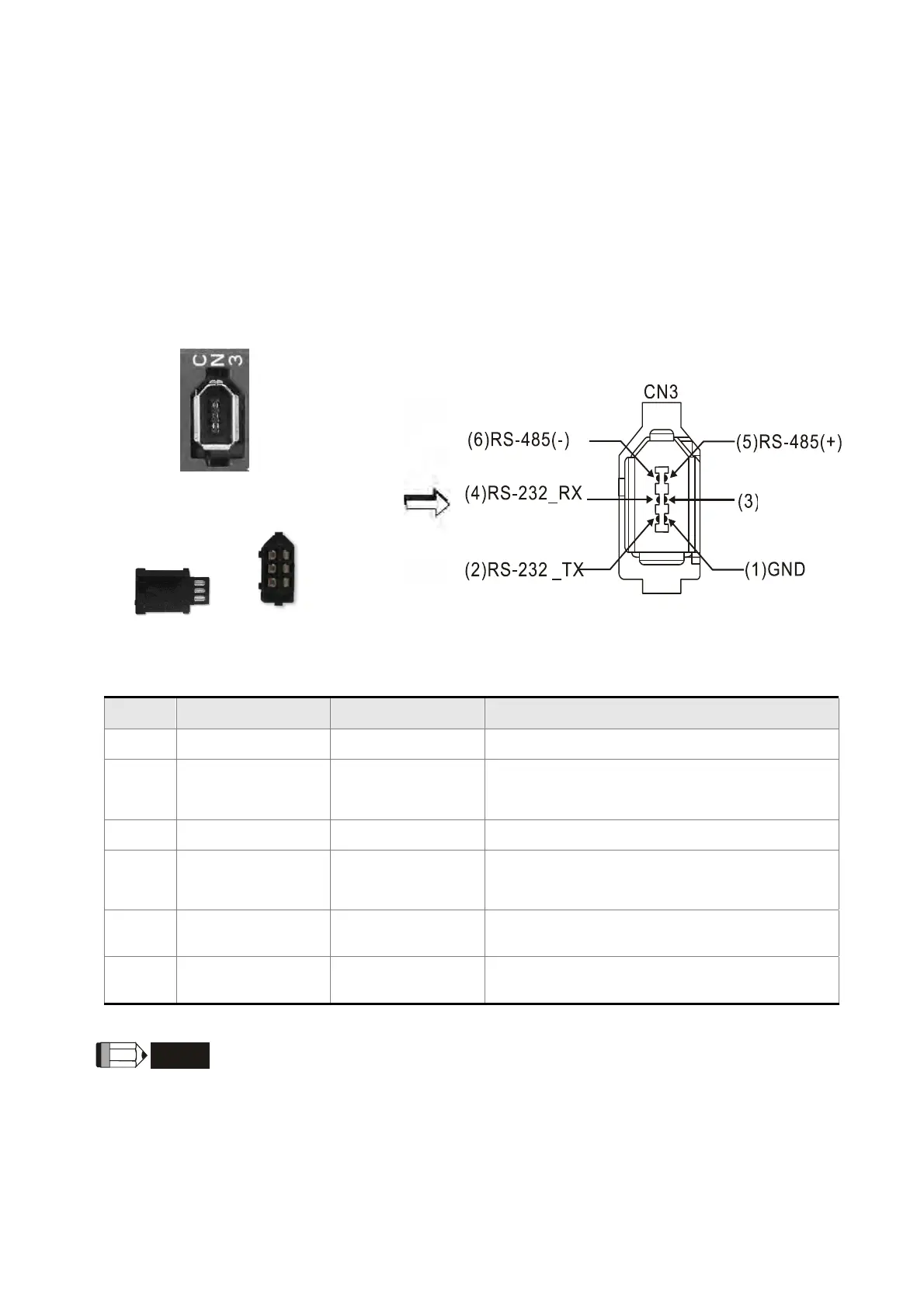
3.5 Wiring of CN3 Connector
3.5.1 Layout of CN3 Connector
The servo drive connects to the personal computer via communication connector. The
user can operate the servo drive via MODBUS, PLC or HMI. There are two common
communication interfaces, RS-232 and RS-485. Both can be set via parameter P3-05.
Among them, RS-232 is more common. Its communication distance is about 15 meter. If
the user selects RS-485, its transmission distance is longer and supports more than one
servo drives for connection.
CN3 Connector
(female)
Side view Rear view
Pin No Signal Name Terminal Symbol Function and Description
1 Signal grounding GND + 5 V connects to the signal terminal
2 RS-232 data
transmission
RS-232_TX The drive transmits the data
The connector connects to RS-232 of PC
3 - - Reserved
4 RS-232 data
receiving
RS-232_RX The drive receives the data
The connector connects to RS-232 of PC
5 RS-485 data
transmission
RS-485(+) The drive transmits the date to differential
terminal (+)
6 RS-485 data
transmission
RS-485(-) The drive transmits the date to differential
terminal (-)
NOTE
1) Please refer to Chapter 9, page 2 for the wiring of RS-485.
2) Two kinds of communication wire of IEEE1394 are commercially
available. One of the internal ground terminals (Pin 1) will short
circuit with the shielding and will damage the drive. Do not connect
GND to the shielding.
Reserved
 Loading...
