Chapter 3 Wiring ASDA-A2R Series
Revision December, 2014
3-13
ECMA-E△1830S (3000 W)
ECMA-F△1830S (3000 W)
ECMA-E△1835S (3500 W)
Please select shielded multi-core and the shielded cable should connect to the SHIELD
end. Please refer to the description of Section 3.1.6.
NOTE
1) Box, (
△
) in servo motor model represents encoder type.
△
=1:
incremental, 20-bit;
△
=2: incremental, 17-bit.
2) Box, () in servo motor model represents brake or keyway / oil seal.
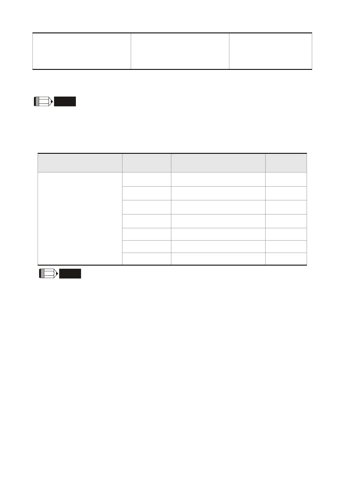
Specification and Definition of Motor Signal Cable
Motor Model Color Definition AWG
ECML-S16S
ECML-S20S
ECML-S25S
ECML-S32S
Black Hall sensor 5V 26
Black / Red Hall sensor 0V 26
White U phase signal of hall sensor 26
Brown V phase signal of hall sensor 26
Blue W phase signal of hall sensor 26
Orange
Temperature signal +
26
Orange / Red
Temperature signal -
26
NOTE
1) U, V, W are the bare wire, which has no connector and terminal.
2) The total length of standard cable is 500mm.
3) The cover of the green grounding cable is heat-shrink tubing. If
users cut off the grounding cable and re-connect it, please connect it
to the shielded net for better noise separation.
4) All signal cable of motor must connect to the servo drive.
 Loading...
