EasyManua.ls Logo

Delta ASD-A2R-1B43 Series User Manual

Delta ASD-A2R-1B43 Series
660 pages
To Next Page IconTo Next Page
To Previous Page IconTo Previous Page
Page #128 background imageLoading...
Page #128 background image
Chapter 4 Panel Display and Operation ASDA-A2R Series
4-12 Revision December, 2014
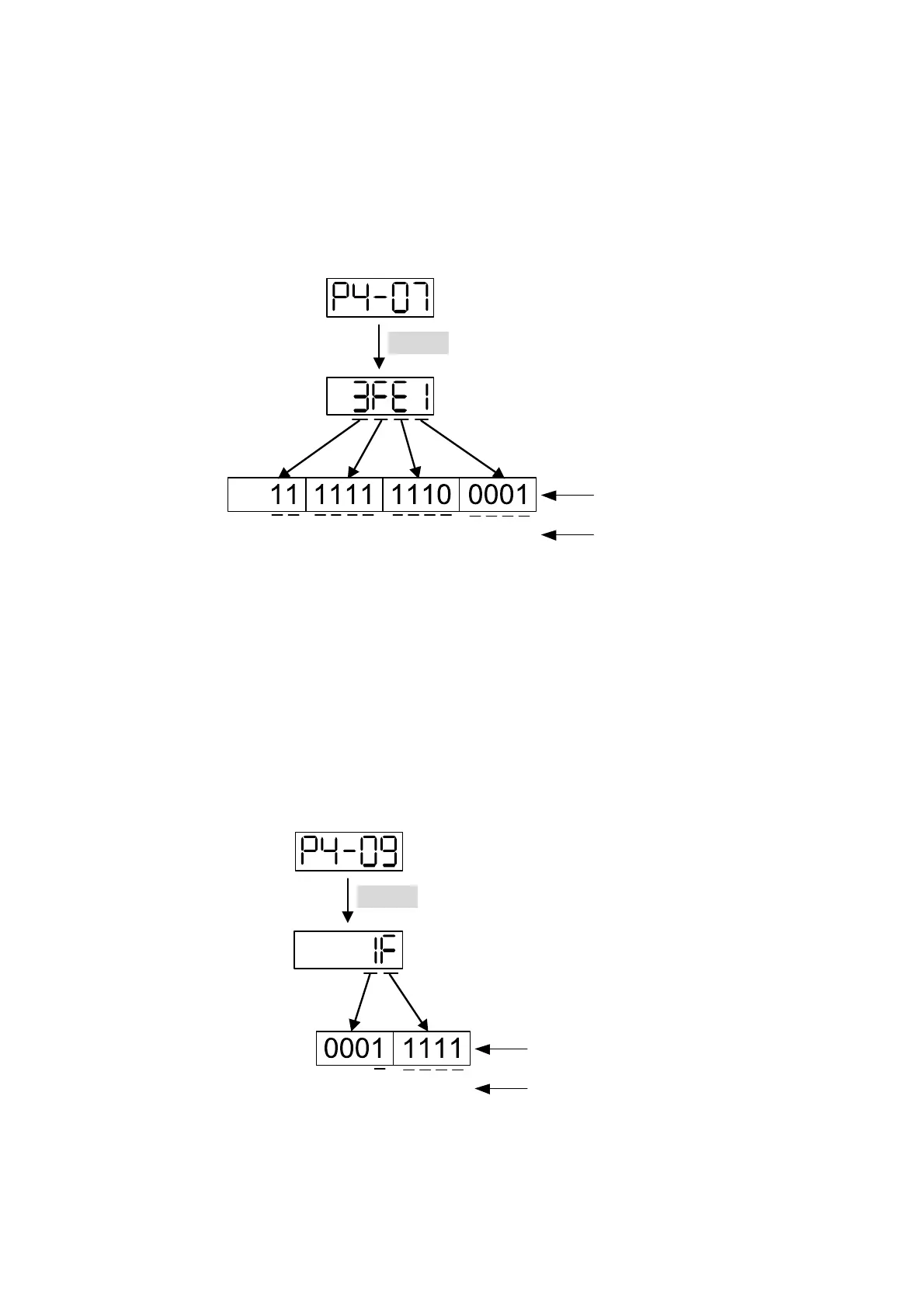
4.4.4 Digital Input Diagnosis Operation
Enter into the Digital Input Diagnosis Mode by the following setting methods. When the
external output signal DI1~DI8 is ON, the corresponding signal will be shown on the
panel. It is displayed by bit. When it shows bit, it means it is ON.
For example, if it shows
3FE1, E is in hexadecimal format, it will be 1100 when it transfers
to binary format. Then, DI6~DI8 is ON.
SET
DI
14
DI
13
DI
12
DI
11
DI
10
DI
9
DI
8
DI
7
DI
6
DI
5
DI
4
DI
3
DI
2
DI
1
Corresponding
DI status
Binary code
The panel displays in
hexadecimal format.
(Display in hexadecimal format)
4.4.5 Digital Output Diagnosis Operation
Enter into the Digital Output Diagnosis Mode by the following setting methods. The
output signal DO1~DO5 is ON and the corresponding signal will be shown on the panel.
It is displayed by bit. When it shows bit, it means it is ON.
For example, if it shows
1F, F is in hexadecimal format, it will be 1111 when it transfers to
binary format. Then, DO1~DO4 is ON.
SET
DO
5
DO
4
DO
3
DO
2
DO
1
Corresponding
DO status
Binary code
The panel displays in
hexadecimal format
(Display in hexadecimal format)

Table of Contents

Question and Answer IconNeed help?

Do you have a question about the Delta ASD-A2R-1B43 Series and is the answer not in the manual?

Delta ASD-A2R-1B43 Series Specifications

General IconGeneral
BrandDelta
ModelASD-A2R-1B43 Series
CategoryServo Drives
LanguageEnglish

Summary

Preface

Safety Precautions

Details critical safety measures and warnings to be observed before and during operation, installation, and wiring.

Chapter 1 Inspection and Model Explanation

Chapter 2 Installation

2.3 Ambient Conditions of Installation

Specifies the environmental requirements for installing the servo drive and motor, including temperature, humidity, and contamination levels.

Chapter 3 Wiring

3.1 Wiring of Delta’s Servo System

Details the wiring methods for Delta's servo systems, including diagrams and notes for peripheral device connections.

3.1.1 Wiring Diagram of Peripheral Devices (connect to Delta’s Servo Motor (Communication Type))

Provides a wiring diagram for connecting peripheral devices to the servo motor using communication interfaces.

3.1.2 Connectors and Terminals of the Servo Drive

Lists and describes all terminal signals and connectors on the servo drive for various functions like power input and communication.

3.1.3 Wiring Method

Illustrates the wiring methods for single-phase and three-phase power supplies, explaining the function of contacts and coils.

3.2 Schematic Diagram of Servo System

Presents schematic diagrams of the servo system, illustrating connections for different models and regenerative resistor configurations.

3.3 I/O Signal (CN1) Connection

Details the I/O signals for CN1, including digital inputs, outputs, encoder signals, and analog command inputs.

3.4 CN2 Connector

Describes the terminal blocks and pin numbers for the CN2 connector, covering both encoder and motor connections.

3.5 Wiring of CN3 Connector

Explains the wiring of the CN3 connector for PC communication via RS-232 and RS-485, including pin definitions.

3.7 CN5 Connector (Full-closed Loop)

Explains the CN5 connector for full-closed loop control, connecting to linear scales or encoders for precise position feedback.

3.8 CN6 Connector (CANopen)

Describes the CN6 connector for CANopen communication, supporting position, torque, and speed modes.

3.10 Standard Wiring Method

Provides standard wiring diagrams for various control modes like Position (PT), Position (PR), Speed, and Torque.

Chapter 4 Panel Display and Operation

4.2 Parameter Setting Procedure

Details the step-by-step procedure for switching between modes and operating within Monitor, Parameter, and Alarm modes.

Chapter 5 Trial Operation and Tuning

5.1 Inspection without Load

Covers the initial inspection steps before powering the servo drive, ensuring no damage or loose parts.

5.2 Apply Power to the Servo Drive

Provides instructions on how to correctly apply power to the servo drive, including wiring checks and power-on display information.

5.3 JOG Trial Run without Load

Details the procedure for performing a JOG trial run without load, recommended for safety and initial testing.

5.6 Tuning Procedure

Provides comprehensive procedures for tuning the servo motor, including inertia estimation and auto/semi-auto tuning.

Chapter 6 Control Mode of Operation

6.1 Selection of Operation Mode

Lists and describes the available single, dual, and multi-mode operations for position, speed, and torque control.

Chapter 7 Motion Control

Chapter 8 Parameters

8.2 List of Parameters

Provides a comprehensive list of all parameters, including their abbreviation, function, default value, and related sections.

8.3 Parameter Description

Offers detailed descriptions for each parameter group, explaining their function, interface, default settings, and related sections.

Chapter 9 Communication

Chapter 10 Troubleshooting

10.1 Alarm of Servo Drive

Lists servo drive alarms, their descriptions, corresponding DO signals, and the servo status for each alarm.

10.4 Causes and Corrective Actions

Explains the common causes and corrective actions for various servo drive alarms like over current, over voltage, and motor errors.

10.5 Corrective Actions after the Alarm Occurs

Provides specific corrective actions for various alarms, including reset procedures and re-powering instructions.

Chapter 11 Specifications

Chapter 12 Setting of Motor Parameters

12.1 Tuning Procedure of Motor Parameters

Guides users through the process of tuning motor parameters using PC software or the panel, emphasizing safety precautions.

Related product manuals