Chapter 3 Wiring ASDA-A2R Series
3-18 Revision December. 2014
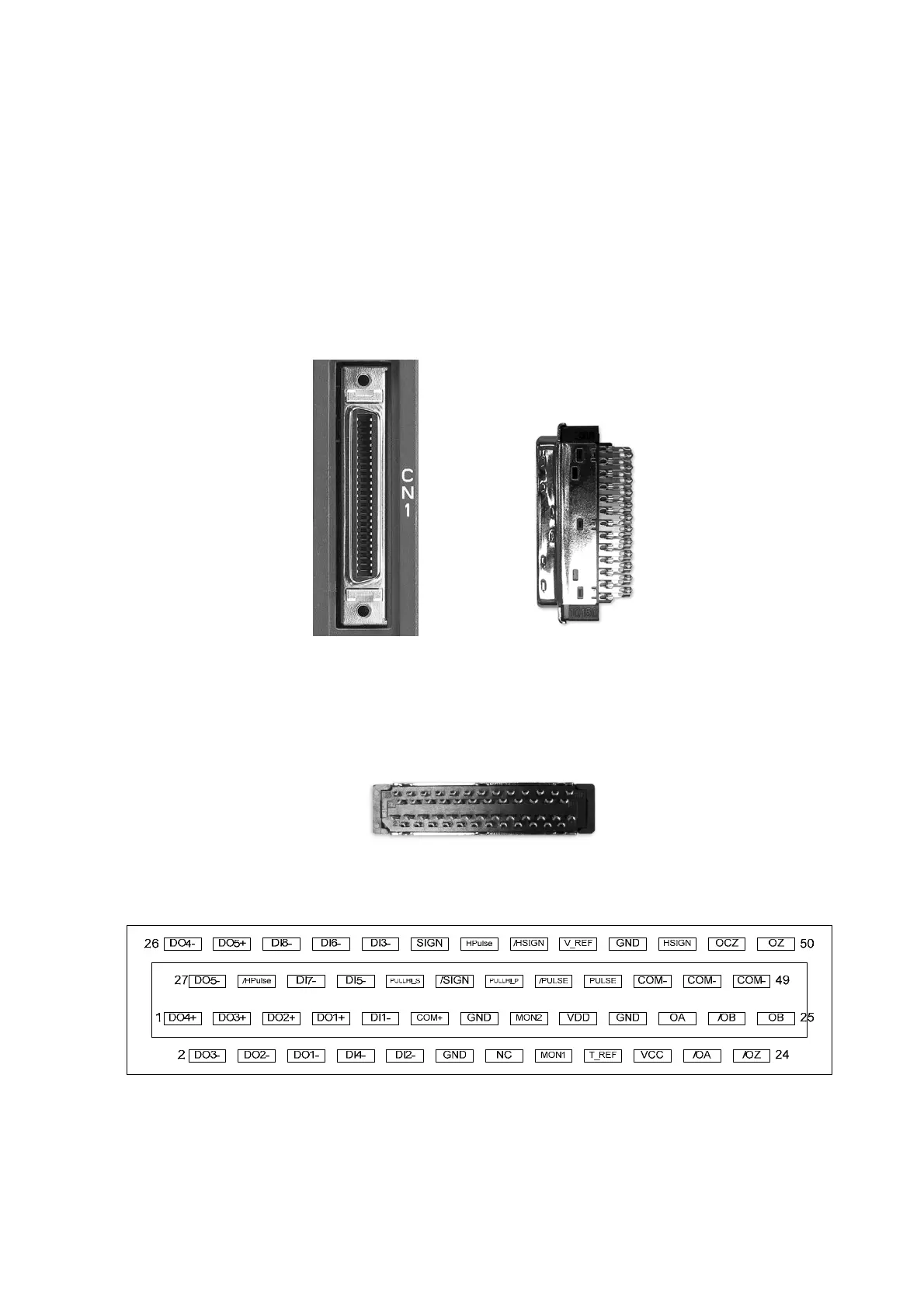
3.3 I/O Signal (CN1) Connection
3.3.1 I/O Signal (CN1) Connector Terminal Layout
In order to have a more flexible communication with the master, 5 programmable Digital
Outputs (DO) and 8 programmable Digital Inputs (DI) are provided. The setting of 8
digital inputs and 5 digital outputs of each axis are parameter P2-10~P2-17 and
parameter P2-18~P2-22 respectively. In addition, the differential output encoder signal,
A+, A-, B+, B-, Z+ and Z-, input of analog torque command, analog speed/position
command and pulse position command are also provided. The followings are the pin
diagrams.
CN1 Connector (female) Side view
Rear view
The rear wiring terminal of CN1 connector
 Loading...
