3 Functions of Devices in DVP-PM
DVP-PM Application Manual
3-75
1. Range: 0 ~ +2,147,483,647
2. Unit: machine unit (cm/min, 10deg/min, inch/min). The unit setting can be modified by b0 and b1 of D1816
(D1896, D1976).
X axis Y axis Z axis A axis
HW LW HW LW HW LW HW LW
D1856 D1936 D2016 D2096
Execution Status
bit# D1856 (D1936, D2016) bit# D1856 (D1936, D2016)
0 Forward pulse output in progress 8 Not defined
1 Reverse pulse output in progress 9 Not defined
2 Operation in progress 10 Not defined
3 Error occurs 11 Not defined
4 Operation pauses 12 Not defined
5 Forward MPG input 13 Not defined
6 Reverse MPG input 14 Not defined
7 Not defined 15 Not defined
X axis Y axis Z axis A axis
HW LW HW LW HW LW HW LW
D1857 D1937 D2017 2097
Error Code
Please see Appendix in Chapter 14 for details.
X axis Y axis Z axis A axis
HW LW HW LW HW LW HW LW
Electronic Gear Ratio
D1858 D1938 D2018 D2098 Numerator of electronic gear ratio
D1859 D1939 D2019 D2099 Denominator of electronic gear ratio
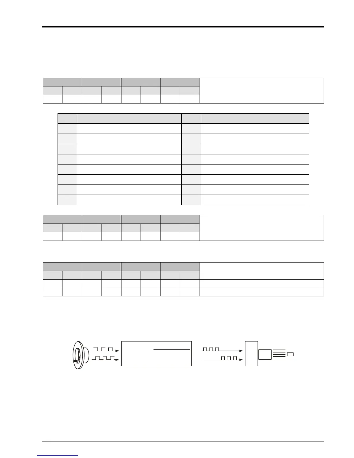
1. When b5 of D1846 (D1926, D2006) is ON, MPG input operation will be enabled.
2. Users can generate A/B phase input pulse by MPG. See the figure below for the relation between input and
output pulses.
FP
RP
D1858(D1938)
D1859(D1939)
Input pulse x
= Output pulse
A-phase
B-phase
Servo Drive
Servo Motor
3. If LSP is enabled during the operation, the forward pulse will be disabled but reverse pulse will be enabled. If LSN
is enabled during the operation, the reverse pulse will be disabled but forward pulse will be enabled.
4. The output frequency is the multiplication result between MPG input pulses and the electronic gear ratio. (D1858
(D1938, D2018), D1859 (D1939, D2019)).

 Loading...


