EATON Managed ePDUt User’s Guide S 164201xxx Rev 1 DRAFT 10−OCT−2008
19
Chapter 5 Using the ePDU
This chapter explains how to use the ePDU. It describes the LEDs and ports on the
front and back panels of the ePDU, and explains how to use the display panel. It also
explains how the circuit breaker works and when the beeper goes off.
Front Panel
The front panel of the 1U and 2U ePDU models consists of a blue LED to the right
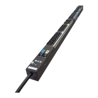
and three connection ports to the left. The front panel of the 0U model consists of
power outlets to connect devices to the ePDU, a display panel, a recessed reset
button, and three connection ports.
Ethernet Ports
The three RJ−45 Ethernet ports, from left to right, are labeled Serial, Feature, and
LAN. Table 1 explains what each port is used for.
Table 1. Ethernet Ports
Port Purpose
Serial Establishing a serial connection between a computer and the ePDU.
Take the null modem cable that was shipped with the ePDU , connect the end with the
RJ−45 connector to the port labeled Serial on the front of the ePDU, and connect the
end with the DB−9F connector to the serial (COM) port on the computer.
Feature For use with Eaton−provided environmental sensors.
LAN Connecting the ePDU to your company’s network.
Connect a standard Category 5e UTP cable to this port and connect the other end to
your network. This connection is necessary to administer the ePDU remotely using the
Web interface.
There are two small LEDs under the LAN port. Green indicates a physical link and
activity, and yellow indicates communication at 10/100 BaseT speeds.
Blue LED
Only the 1U and 2U models have a blue LED on the front panel. The blue LED on the
right side of the front panel is lit solid when the ePDU is plugged in.
NOTE If the blue LED is flashing, one of the two power supplies in the ePDU is not functional.
NOTE When the ePDU is powered on, the power−on self test and software loading takes approximately
40 seconds. Once the software has booted up, the outlet LEDs and the meter illuminate.

 Loading...