EasyManuals Logo
Home>Emerson>Controller>FloBoss 107

Emerson FloBoss 107 User Manual

Emerson FloBoss 107
152 pages
To Next Page IconTo Next Page
To Previous Page IconTo Previous Page
Page #103 background imageLoading...
Page #103 background image
FloBoss 107 Instruction Manual
Revised June-2017 Communications 5-17
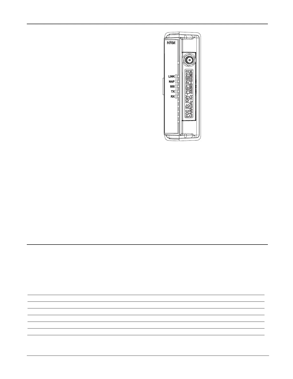
Figure 5-17. Network Radio Module
5.9.1 Installing the NRM
The NRM is designed to be plug-and-play and requires no wiring. The
NRM can be installed in slot 1 or 2 in the FB107.
Depending on the enclosure you choose to surround the node and protect
it from the environment, you may need additional cabling between the
antenna and the connection on the module itself. For additional details on
antenna, cabling, and enclosure installation instructions, refer to the
Distributed Network Module Instruction Manual (part D301727X012).
5.10 Additional Technical Information
Refer to the following documents (available at
www.EmersonProcess.com/Remote) for additional and most-current
information on each of the modules discussed in this chapter.
Table 5-5. Additional Technical Information
Name
Form Number
Part Number
FloBoss™ 107 Communication Modules
FB107:COM
D301237X012
FloBoss™ 107 Multi-Variable Sensor (MVS) Modules
FB107:MVS
D301239X012
FloBoss™ 107 LCD Touchpad
FB107:LCD
D301241X012
FloBoss™ 107 Enhanced Communication Module
FB107:ECM
D301642X012
FloBoss™ 107 Dial-Up Modem Module
FB107:DIAL
D301643X012
FloBoss™ 107 Network Radio Module
FB107:NRM
D301731X012

Table of Contents

Other manuals for Emerson FloBoss 107

Questions and Answers:

Question and Answer IconNeed help?

Do you have a question about the Emerson FloBoss 107 and is the answer not in the manual?

Emerson FloBoss 107 Specifications

General IconGeneral
BrandEmerson
ModelFloBoss 107
CategoryController
LanguageEnglish

Related product manuals