FloBoss 107 Instruction Manual
Revised June-2017 Power Connections 3-1
Chapter 3 – Power Connections
In This Chapter
3.1 Power Input Descriptions ................................................................... 3-1
3.2 Determining Power Consumption....................................................... 3-3
3.2.1 Summary ............................................................................... 3-6
3.3 Wiring Connections ............................................................................ 3-6
3.4 Wiring Power to the CPU Module....................................................... 3-7
This chapter describes wiring with FB107 with power from a dc voltage
source.
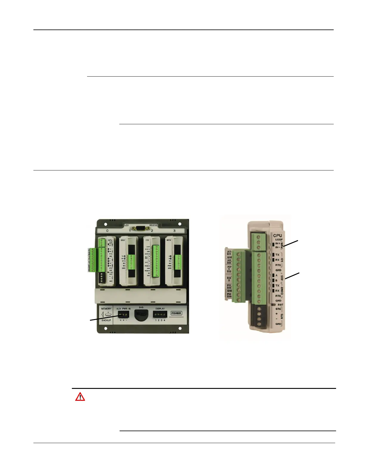
3.1 Power Input Descriptions
The FB107’s power terminals (either through the AUX PWR IN
connection on the base unit or through the power connections on the CPU
module) convert external input power to the voltage levels the FB107’s
electronics require.
When installing units in a hazardous area, make sure all installation
components selected are labeled for use in such areas. Installation
and maintenance must be performed only when the area is known to
be non-hazardous. Installation in a hazardous area could result in
personal injury or property damage.

 Loading...


