FloBoss 107 Instruction Manual
Revised June-2017 Power Connections 3-7
3.4 Wiring Power to the CPU Module
Typically, you would use the AUX PWR IN connection on the FB107
base unit to power the FB107. Alternately, you can wire power directly
into the CPU module.
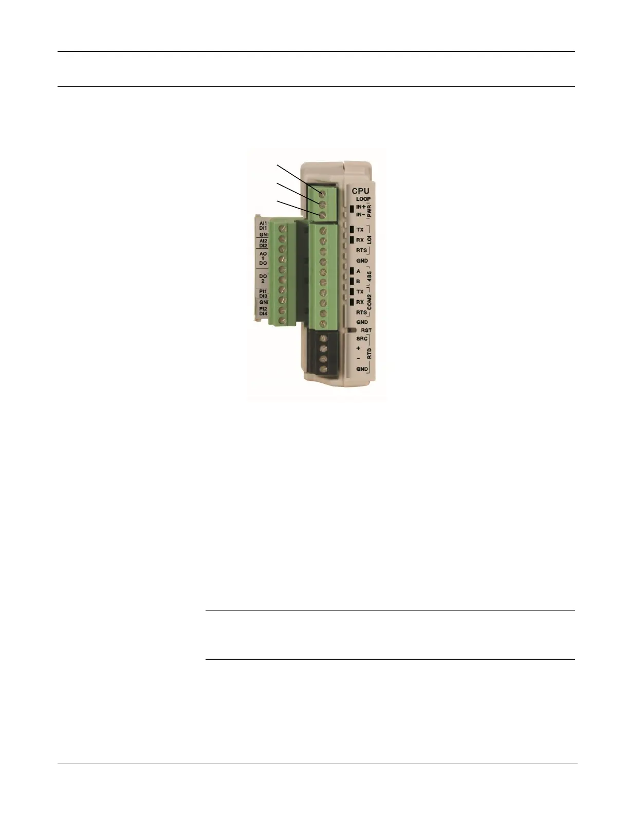
Figure 3-2. Power Wiring, CPU Module
The CPU module connectors use compression terminals. The input power
termination (IN+ / IN) uses a removable connector and accommodates
wiring size 16 to 24 AWG. Refer to Section 3.3, Wiring Connections.
The FB107 accepts input voltages from 8.0 to 30.0 volts at the PWR IN+
/ IN input power terminals
Labels on the CPU (see Figure 3-2) identify the IN+ terminal for positive
power connection (8.0 to 30.0 volts power) and the IN terminal for
negative power connection (Battery Common).
Note: Follow good wiring practices when sizing, routing, and
connecting power wiring. All wiring must conform to state, local,
and NEC codes.

 Loading...


