EasyManuals Logo
Home>Emerson>Controller>FloBoss 107

Emerson FloBoss 107 User Manual

Emerson FloBoss 107
152 pages
To Next Page IconTo Next Page
To Previous Page IconTo Previous Page
Page #86 background imageLoading...
Page #86 background image
FloBoss 107 Instruction Manual
4-28 Inputs and Outputs Revised June-2017
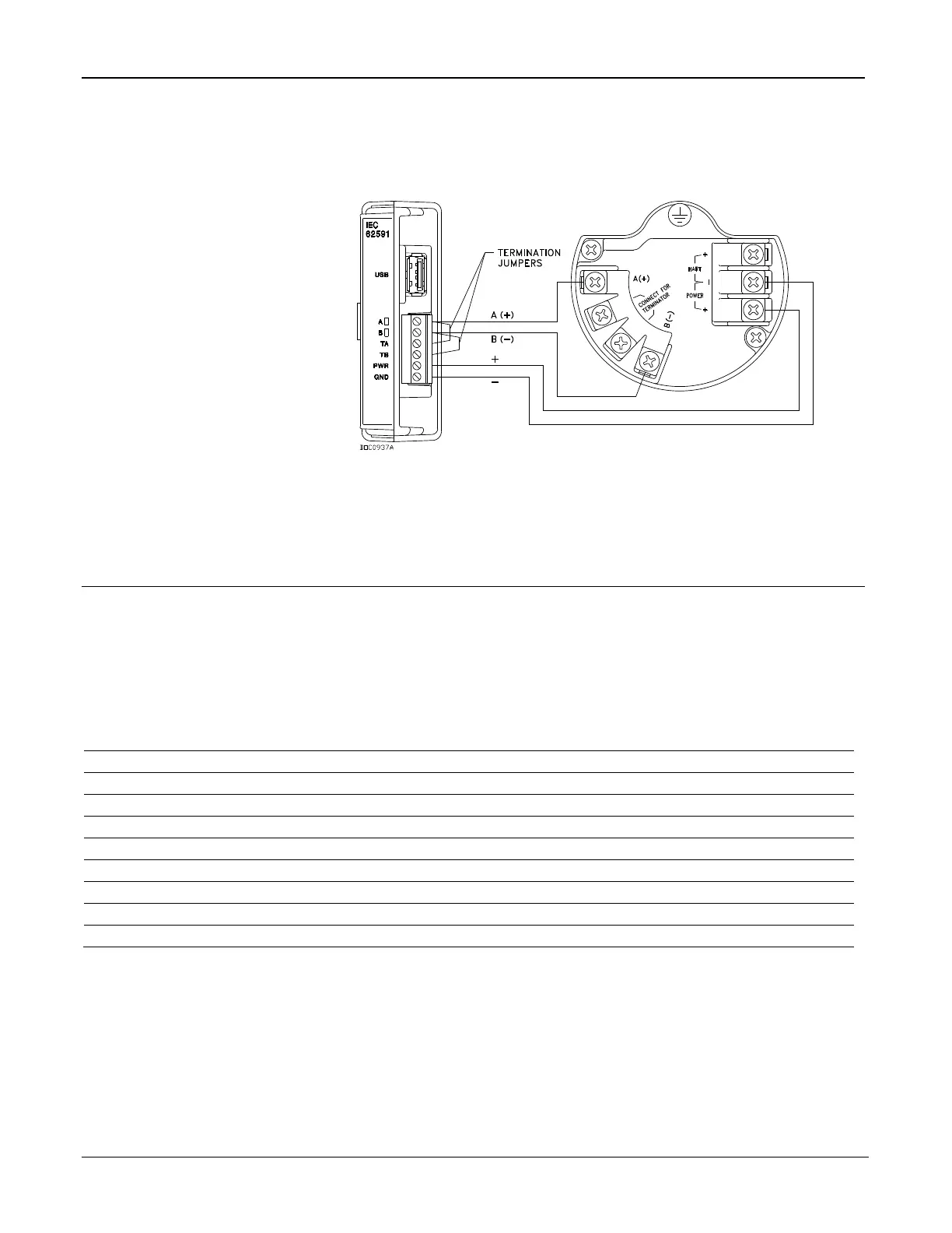
4.18.1 Wiring the IEC 62591 Module
Figure 4-31 shows the IEC 62591 module wired to a Smart Wireless
Field Link.
Figure 4-31. FB107 IEC 62591 Module Power and Data Wiring to Field
Link
4.19 Additional Technical Information
Refer to the following documents (available at
www.EmersonProcess.com/Remote) for additional and most-current
information on each of the modules discussed in this chapter.
Table 4-4. Additional Technical Information
Name
Form Number
Part Number
FloBoss™ 107 8-Point AI/DI Module
FB107:AIDI
D301464X012
FloBoss™ 107 6-Point Analog Output / Discrete Output Module
FB107:AODO
D301637X012
FloBoss™ 107 Discrete Output Relay Module
FB107:DOR
D301466X012
FloBoss™ 107E Enclosure Options (for Pulse Inputs)
FB107:ENC
D301276X012
FloBoss™ 107 Application Module
FB107:APP
D301665X012
FloBoss™ 107 Resistance Temperature Device (RTD) Module
FB107:RTD
D301638X012
FloBoss™ 107 6-Point Analog Output / Discrete Output Module
FB107:AODO
D301637X012
FloBoss™ 107 HART® Module
FB107:HART
D301639X012
FloBoss™ 107 IEC 62591 Interface
FB107:62591
D301713X012

Table of Contents

Other manuals for Emerson FloBoss 107

Questions and Answers:

Question and Answer IconNeed help?

Do you have a question about the Emerson FloBoss 107 and is the answer not in the manual?

Emerson FloBoss 107 Specifications

General IconGeneral
BrandEmerson
ModelFloBoss 107
CategoryController
LanguageEnglish

Related product manuals