FloBoss 107 Instruction Manual
Revised June-2017 Sensors and Transducers 6-9
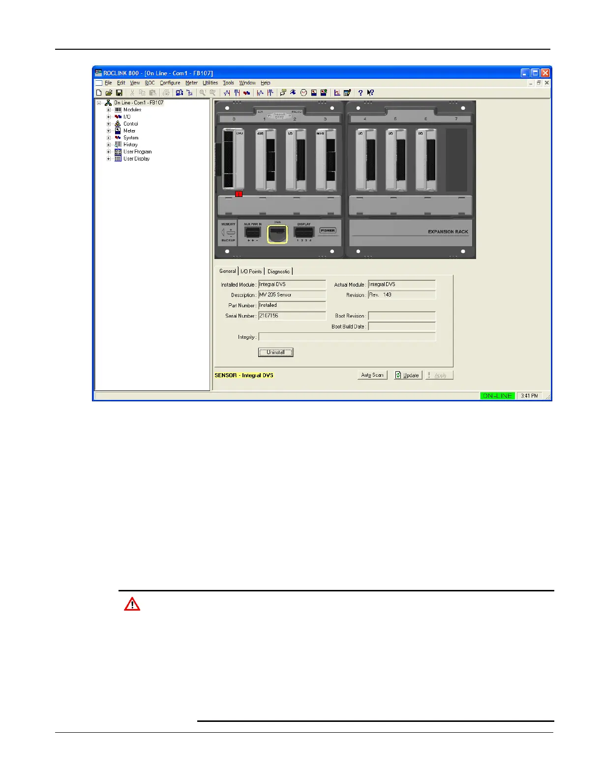
Figure 6-6. FB107 Graphical Interface for DVS
The tabs—General, I/O Points, and Diagnostic—provide
information (mostly read-only) on the DVS.
6.2.2 Physically Connecting a DVS
Run piping from the meter run to the DVS. Both the static and
differential pressures attach to female ¼-18 NPT connections on
the bottom of the DVS. The FB107 is an upstream device: the
static pressure line normally connects to the high pressure side
(indicated by an H cast into the side of the DVS housing).
To protect the DVS’s differential cell, open the bypass valve on the
valve manifold PRIOR to isolating the sensor from the process. This
keeps one side of the differential sensor from being subjected to high
pressure while the other side has no applied pressure. This is required
when you calibrate either differential or static pressure.
To protect the DVS’s differential cell, DO NOT close the bypass valve
on the valve manifold until after process pressure has been reapplied.
This keeps one side of the differential sensor from being subjected to
high pressure while the other side has no applied pressure.

 Loading...


