FloBoss 107 Instruction Manual
4-6 Inputs and Outputs Revised June-2017
6. Wire the I/O module. Refer to Section 4.4, Wiring a Module.
7. Replace the wire channel cover.
Never connect the sheath surrounding shielded wiring to a signal
ground terminal or to the common terminal of an I/O module or CPU I/O
assembly. Doing so makes the I/O module susceptible to static
discharge, which can permanently damage the I/O. Connect the shielded
wiring sheath only to a suitable earth ground.
8. Return power to the FB107.
9. Connect to ROCLINK 800 and log in.
10. Configure the I/O point.
Note: You must perform a power re-start to enable the ROCLINK 800
software to identify the module.
4.3 Removing a Module
To remove an I/O module:
1. Remove power from the FB107.
2. Remove the wiring (or the removable terminal blocks) from the
module.
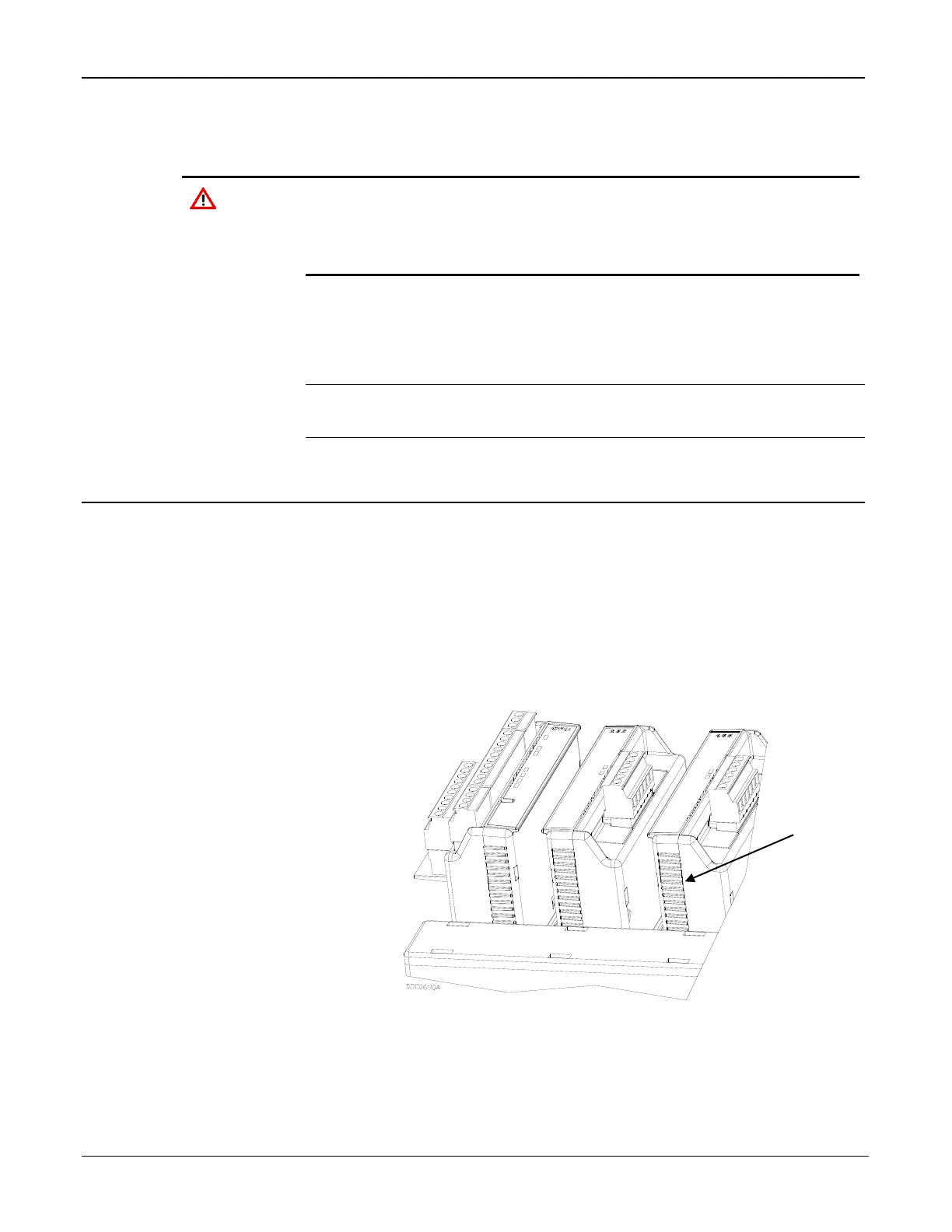
3. Place your fingers on the ridged edges on both sides of the module
and pull out gently (see Figure 4-3). The cover should slide forward
and stop, releasing the module lock.
Figure 4-3. Ridged Edges on Modules
4. Gently rock the module until it releases from the backplane and you
can remove it from the base unit or expansion rack.

 Loading...


