EasyManuals Logo
Home>Emerson>Controller>FloBoss 107

Emerson FloBoss 107 User Manual

Emerson FloBoss 107
152 pages
To Next Page IconTo Next Page
To Previous Page IconTo Previous Page
Page #68 background imageLoading...
Page #68 background image
FloBoss 107 Instruction Manual
4-10 Inputs and Outputs Revised June-2017
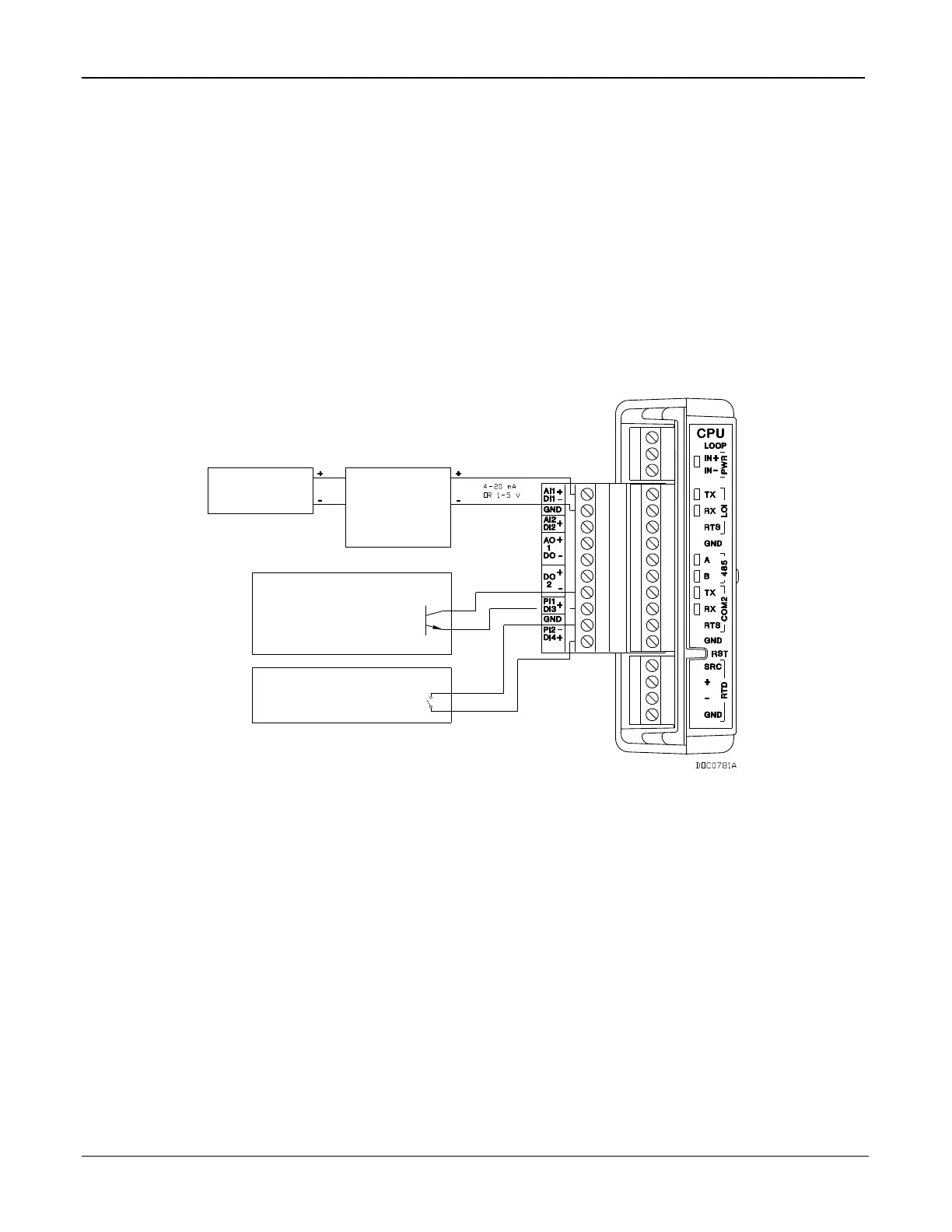
The I/O module only supports 24 volts dc loop output power. The CPU
module’s I/O assembly uses the CPU’s loop power output and ground
connections.
The intent of the loop output power is to power devices (such as
Rosemount transmitters) that require 24 volts dc to ground and then send
the FB107 a 4 to 20 mA signal based on pressure, temperature, level and
such.
The 10-volt loop output power is intended for low power transmitters that
send a 1 to 5 volts dc rather than a 4 to 20 mA signal.
The loop current is designed to deliver 80 mA to power two field devices
that connect back to the two analog inputs.
EXTERNALLY
POWEREDPOWER
EXTERNAL
DEVICE
ANALOG
-
-
+
DISCRETE DEVICE
EXTERNALLY POWERED
CONTACT-CLOSURE DEVICE
DISCRETE DEVICE
EXTERNALLY POWERED
OPEN COLLECTOR DEVICE
OR
OPEN DRAIN TYPE
+
Figure 4-6. Loop Output Power for the CPU Module’s Optional I/O Assembly

Table of Contents

Other manuals for Emerson FloBoss 107

Questions and Answers:

Question and Answer IconNeed help?

Do you have a question about the Emerson FloBoss 107 and is the answer not in the manual?

Emerson FloBoss 107 Specifications

General IconGeneral
BrandEmerson
ModelFloBoss 107
CategoryController
LanguageEnglish

Related product manuals