EasyManuals Logo
Home>Emerson>Controller>FloBoss 107

Emerson FloBoss 107 User Manual

Emerson FloBoss 107
152 pages
To Next Page IconTo Next Page
To Previous Page IconTo Previous Page
Page #81 background imageLoading...
Page #81 background image
FloBoss 107 Instruction Manual
Revised June-2017 Inputs and Outputs 4-23
Table 4-3. RTD Wiring
Terminal
Wiring Color
Designation
4-Wire RTD
3-Wire RTD
SRC
Red
Signal source current positive input
SRC
SRC
+
Red
+ RTD
+ RTD
+ RTD
White
RTD
RTD
RTD
GND
White
Negative ground return reference
GND
GND jumper to
RTD
Note: The wire colors for the RTD being used may differ.
A
Red
B
White
C
Jumper
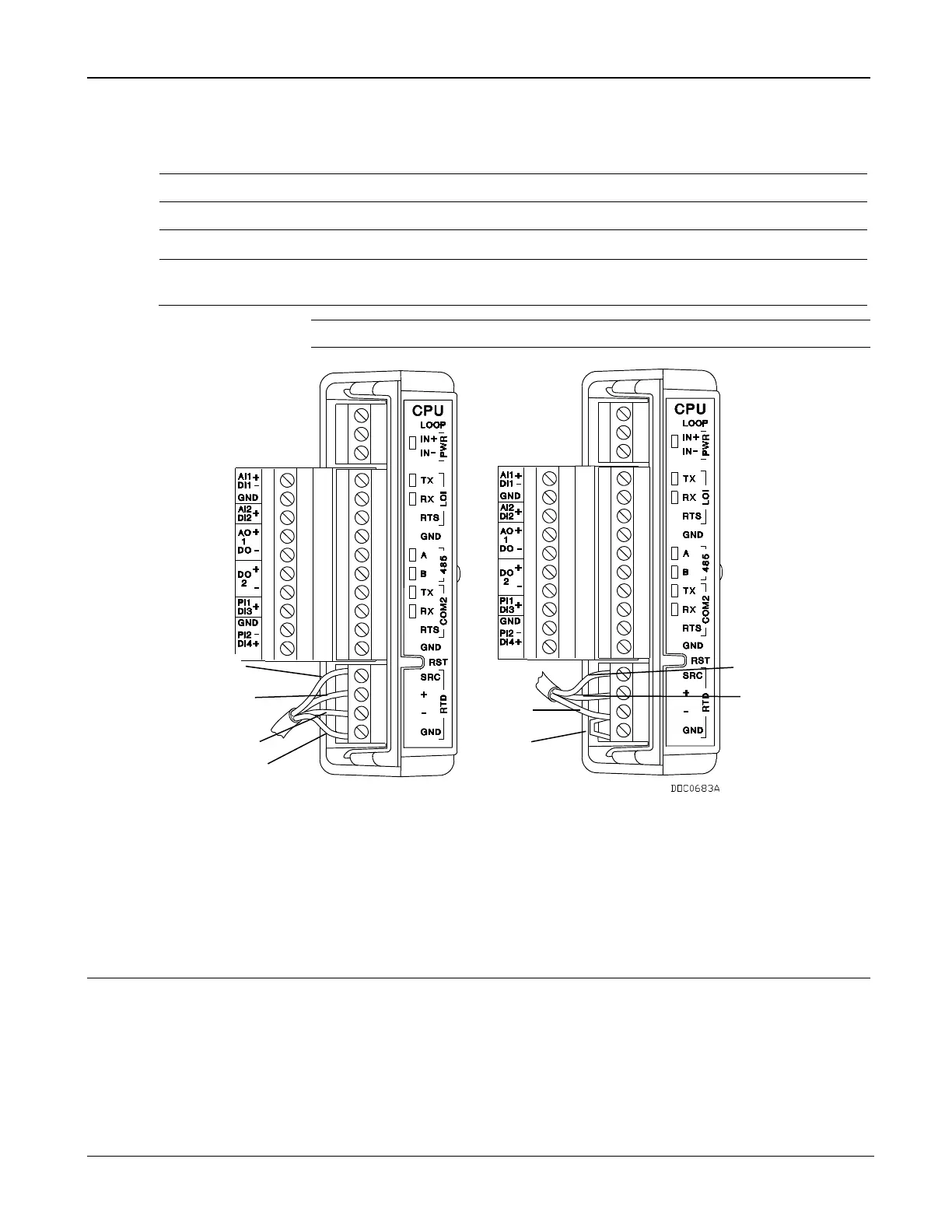
Figure 4-20. RTD Sensor Wiring (on CPU Module)
4.15 6-Point AO/DO Module
This module provides six single-ended analog outputs or field effect
transistor (FET) switch discrete outputs. You use ROCLINK 800
Configuration software to configure each individual channel.
All modules have removable terminal blocks for convenient wiring and
servicing. The terminal blocks can accommodate size 16 to 24 American
Wire Gauge (AWG).
RED
RED
WHITE
Jumper
RED
RED
WHITE
WHITE
A
A
A
A
B
B
B
C

Table of Contents

Other manuals for Emerson FloBoss 107

Questions and Answers:

Question and Answer IconNeed help?

Do you have a question about the Emerson FloBoss 107 and is the answer not in the manual?

Emerson FloBoss 107 Specifications

General IconGeneral
BrandEmerson
ModelFloBoss 107
CategoryController
LanguageEnglish

Related product manuals