Home
Emerson
Controller
FloBoss 107
Emerson FloBoss 107 User Manual
5
of 1
of 1 rating
152 pages
Give review
Manual
Specs
To Next Page
To Next Page
To Previous Page
To Previous Page
Loading...
FloBoss 107 Inst
ruction M
anua
l
5-
12
Comm
unications
Rev
ised June-2017
Select the
Update Driver
button.
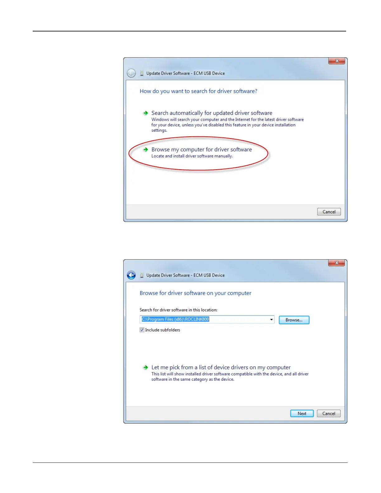
Figure 5-9. Update Browser Software
Select
Browse my computer for driver software
.
Figure 5-10. Update Browser Software
97
99
Table of Contents
Default Chapter
3
Table of Contents
3
Chapter 1 - General Information
7
Scope of Manual
8
Floboss 107 Overview
8
Requirements
8
Device
8
Devices
8
Hardware
11
Processor and Memory
12
Backplane
12
Expansion Rack
12
Central Processing Unit (CPU)
12
Battery and Super-Capacitor
14
Built-In Inputs and Outputs
14
Built-In Communications
14
Built-In Resistance Thermal Device (RTD)
16
Built-In Loop Output Power
16
Optional Inputs and Outputs
16
Optional Communication Modules - COM3
17
Enhanced Communication Module
17
Optional Multi-Variable Sensor (MVS)
18
Optional Integral Sensors
18
Optional License Key
18
Optional Enclosures
18
Optional LCD Touchpad
19
Polycarbonate Enclosure with a DVS Module
19
Firmware
20
History Points
21
Extended History
21
Alarm Log
22
Event Log
23
Security
23
I/O Database
24
Function Sequence Tables (FST)
24
PID Control
24
Spontaneous-Report-By-Exception (SRBX) Alarming
25
Softpoints
25
Opcodes
25
Pass through Communications
25
ROC and Modbus Protocols
25
User C Programs
26
ROCLINK ™ 800 Configuration Software
26
Roclink
26
Product Electronics
28
Real-Time Clock
28
Diagnostic Monitoring
28
Automatic Self Tests
28
Low Power Mode
29
Flow Measurements
29
Security Gateway
30
Additional Technical Information
31
Chapter 2 - Installation and Use
33
Installation Requirements
33
Environmental Requirements
33
Site Requirements
34
Side and Front View of Floboss 107 Base Unit
35
Compliance with Hazardous Area Standards
36
Power Installation Requirements
36
Grounding Installation Requirements
37
Power Connection on Base Unit
37
I/O Wiring Requirements
38
Installing the Floboss 107 and Expansion Rack
39
Required Tools
39
Installing the Floboss 107 Without an Expansion Rack
39
Installing the Floboss with an Expansion Rack
40
Adapter Plate (FB107 Base Unit)
40
Expansion Rack
41
Adapter Plate (FB107 Expansion Rack)
41
Removing an Expansion Rack
42
Removing and Installing Module Slot Covers
43
Removing and Installing Wire Channel Covers
43
Memory Backup Battery
44
Removing and Installing the Battery
44
Central Processor Unit (CPU)
45
Removing the CPU Module
47
Installing the CPU Module
48
Resetting the CPU
48
License Keys
48
Startup and Operation
49
Startup
49
Operation
49
Chapter 3 - Power Connections
51
Power Input Descriptions
51
Determining Power Consumption
53
Wiring Connections
56
Summary
56
Wiring Power to the CPU Module
57
Chapter 4 - Inputs and Outputs
59
I/O Description
59
CPU Module
60
Module's Optional I/O Assembly
60
I/O Module
61
Installing a Module
63
Removing a Module
64
Wiring a Module
65
Selecting the Type of I/O
65
Analog Inputs (AI)
67
Wiring the Analog Inputs
67
Loop Output Power for the CPU
68
8-Point Analog Input/Digital Input (AI/DI) Module
69
Wiring the 8-Point AI/DI
69
Loop Output Power for the I/O Module
69
DI Wiring
70
Analog Outputs (AO)
71
Wiring the Analog Outputs
71
Discrete Inputs (DI)
72
Wiring the Discrete Inputs
73
Discrete Outputs (DO)
73
Wiring the Discrete Outputs
74
4.11 Discrete Outputs Relay (DOR) Module
75
Discrete Output Wiring - High Side Switch(on CPU Module)
75
Discrete Output Wiring - Low Side Switch (on CPU Module )
75
Discrete Output Relay Module Wiring (High Side Switch)
76
Wiring the Discrete Output Relays
76
Pulse Inputs (PI)
77
Wiring the Pulse Inputs
77
Discrete Output Relay Module Wiring (Low Side Switch)
77
4.13 Application (APP 485) Module
78
Wiring the Application Module
78
Pulse Input Wiring (on CPU Module)
78
4.14 Resistance Temperature Detector (RTD) Input
80
Wiring the RTD Input
80
4.15 6-Point AO/DO Module
81
RTD Sensor Wiring (on CPU Module)
81
Wiring the 6-Point AO/DO Module
82
HART Module
82
Discrete Output High Side Switch Wiring
82
Wiring the HART Module
83
4.17 Resistance Temperature Detector (RTD) Module
84
Wiring the RTD Module
84
4.18 IEC 62591 Module
85
Wiring the IEC 62591 Module
86
4.19 Additional Technical Information
86
FB107 IEC 62591 Module Power and Data Wiring to Field Link
86
Chapter 5 - Communications
87
Communications Overview
87
Eia-232
88
Installing/Removing a Communication Module
91
Wiring the Local Operator Interface (LOI) Port
91
5.3.1 Using the LOI
92
Wiring EIA-485 (RS-485) Communications
92
Wiring EIA-232 (RS-232) Communications
93
Eia-485
93
Liquid Crystal Display (LCD) Touchpad
94
Enhanced Communication Module (ECM)
95
Activating the USB Port
96
Device Manager
97
Update Browser Software
98
Pop-Up Menu
100
Dial-Up Modem Module
101
Communication Parameters
101
Network Radio Module (NRM)
102
Installing the NRM
103
5.10 Additional Technical Information
103
Network Radio Module
103
Chapter 6 - Sensors and Transducers
105
Multi-Variable Sensor (MVS) Module Overview
105
Installing/Removing an MVS Module
108
Configuring a Multi-Drop MVS Module Setup
108
Lightning Protection
110
Dual Variable Sensor (DVS) Overview
111
Installing/Removing a DVS
112
Physically Connecting a DVS
113
Configuring a DVS
114
Pressure Module (PIM) Overview
114
Installing/Removing a Pressure Module
115
Configuring a Pressure Module
117
6.4 Additional Technical Information
118
Chapter 7 - Troubleshooting
119
General Guidelines
119
Graphical User Interface (GUI)
120
Checklists
122
Leds
122
Serial Communications
122
Inputs/Outputs
123
Preserving Configuration and Log Data
124
ROCLINK 800 Configuration Software
124
Powering up
125
Multi-Variable Sensor (MVS)
125
Resistance Temperature Detector (RTD)
125
IEC 62591 Module
126
Network Radio Module (NRM)
126
Procedures
126
Resetting the FB107
127
Restarting and Reconfiguring the FB107
127
Troubleshooting Analog Inputs
128
Troubleshooting Analog Outputs
129
Troubleshooting Discrete Inputs
130
Troubleshooting Discrete Outputs
130
Troubleshooting Pulse Inputs
131
Troubleshooting RTD Inputs
131
Troubleshooting the Multi-Variable Sensor (MVS)
133
Troubleshooting the Enhanced Comm Module (ECM)
134
Troubleshooting the Dual Variable Sensor (DVS)
134
Troubleshooting the Pressure Module (PIM)
135
Troubleshooting AI/DI
136
Troubleshooting the Discrete Output Relay (DOR)
136
Appendix A - Glossary
137
Electromagnetic Interference
139
Other manuals for Emerson FloBoss 107
Site Considerations For Equipment Installation, Grounding, And Wiring Manual
42 pages
5
Based on 1 rating
Ask a question
Give review
Questions and Answers:
Need help?
Do you have a question about the Emerson FloBoss 107 and is the answer not in the manual?
Ask a question
Emerson FloBoss 107 Specifications
General
Brand
Emerson
Model
FloBoss 107
Category
Controller
Language
English
Related product manuals
Emerson FloBoss S600+
156 pages
Emerson FL
16 pages
Emerson TARTARINI FL Series
52 pages
Emerson FD113
4 pages
Emerson FXMP25
66 pages
Emerson Fisher L2
16 pages
Emerson FISHER 92S
24 pages
Emerson FISHER 657
32 pages
Emerson Fisher 67C
12 pages
Emerson Fisher R622
8 pages
Emerson Fisher 627H
24 pages
Emerson Fisher 2052
20 pages