FloBoss 107 Instruction Manual
6-4 Sensors and Transducers Revised June-2017
The interface circuit allows the transmitter to connect to and
communicate with an FB107 using a serial 2-wire EIA-485 (RS-
485) connection.
6.1.1 Installing/Removing an MVS Module
All FB107 modules are designed for ease of installation and
removal. Refer to Installing a Module, Removing a Module, and
Wiring a Module in Chapter 4, Inputs and Output, for specific
instructions.
Note: Modules contain no user-serviceable components.
You can install an MVS module in any slot on the FB107 base
unit or expansion rack with the exception of slot 0, which is
reserved for the CPU.
Never connect the sheath surrounding shielded wiring to a signal
ground terminal or to the common terminal of a MVS module
assembly. Doing so makes the MVS module susceptible to static
discharge, which can permanently damage the module. Connect
the shielded wiring sheath only to a suitable earth ground.
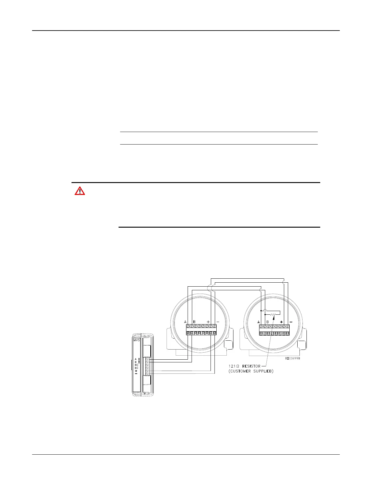
6.1.2 Configuring a Multi-drop MVS Module Setup
The multi-drop (“daisy-chain”) transmitter wiring configuration is
the preferred configuration for the FB107 (see Figure 6-2).
Figure 6-3. MVS Multi-Drop Configuration with Two Transmitters

 Loading...


