FloBoss 107 Instruction Manual
Revised June-2017 Inputs and Outputs 4-19
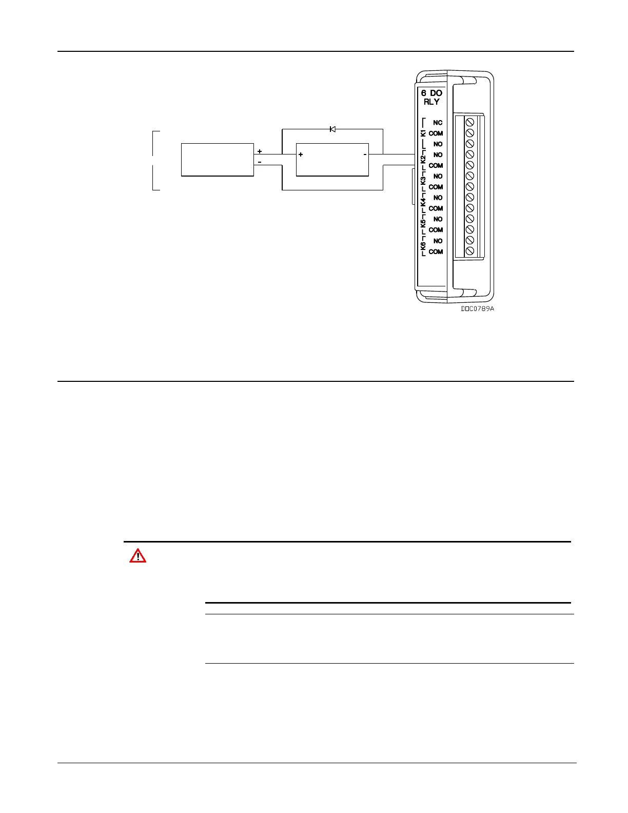
SWITCHED
DEVICESUPPLY
POWER
DO2-DO6
LOW SIDE SWITCH
Figure 4-16. Discrete Output Relay Module Wiring (Low Side Switch)
4.12 Pulse Inputs (PI)
Pulse inputs (PI) processes signals from pulse-generating devices and
provide a calculated rate or an accumulated total over a configured
period. The FB107 pulse input circuits are physically the same as the
discrete inputs. The pulse input routes to a pulse accumulator, where the
pulses are counted and accumulated.
The PI is most commonly used to interface to open collector/open drain
type solid-state devices. Use the PI to interface to self-powered devices.
Acceptable PI voltage levels range between 0.5 volts dc (low) and 1.5
volts dc (high).
The pulse input is designed to operate with non-powered devices,
such as “dry” contacts or isolated solid-state switches. Use of the PI
with externally powered devices may cause improper operation or
damage.
Note: Select PI as the I/O Type for the selectable pulse inputs/discrete
inputs when you configure it for use as a pulse input. Refer to
Figure 4-5.
4.12.1 Wiring the Pulse Inputs
Figure 4-17 shows the terminals on the CPU module for connecting the
PI wiring. The + terminal is a positive source voltage; the GND terminal
is the signal return.

 Loading...


