FloBoss 107 Instruction Manual
7-10 Troubleshooting Revised June-2017
5. Select the configuration file you desire to restore.
6. Click Download to restore the configuration.
7.4.3 Troubleshooting Analog Inputs
Before you can determine if an analog input point is operating properly,
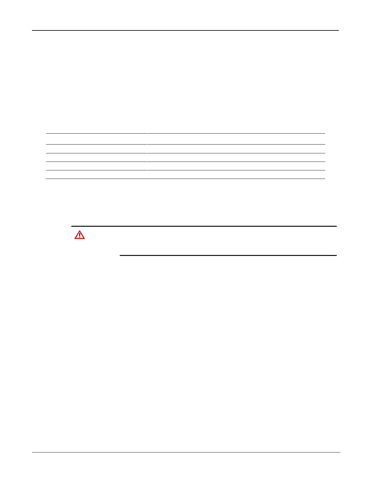
you must first know its configuration. Table 7-1 shows typical
configuration values for an analog input:
Table 7-1. Analog Input Module Typical Configuration Values
1 volt dc across the + and the COM terminal by a multimeter
5 Volts dc across the + and the COM terminal by a multimeter
1
The 8-channel AI/DI module has default values of 800 and 4000.
Calibration source of 1 to 5 volts dc or 4-20 mA
Multimeter
PC running ROCLINK 800 software
Failure to exercise proper electrostatic discharge precautions, such
as wearing a grounded wrist strap may reset the processor or
damage electronic components, resulting in interrupted operations.
1. Remove the field device connected to the transmitter.
2. Set the multimeter to measure voltage and connect it across the + and
GND terminals.
3. Connect to ROCLINK 800.
4. Select Configure > I/O > AI Points.
5. Select the correct analog input point number.
6. Install a voltage source of 1 to 5 volts dc and verify the following
readings:
When supplying 1 volt dc input, AI should indicate 0% EU.
When the reading goes outside the calibrated 0% and 100% A/D
counts, ROCLINK 800 indicates point fail and the input reads and
holds the last know good value or go to a user-defined value as
determined by the AI configuration.
When supplying 5 volts dc, AI should indicate 100% EU.
7. Remove the test equipment.

 Loading...


